Introduction
In this lab, we'll implement a technique called Shadow Mapping. Shadows greatly increase the realism of computer generated images, and shadow mapping is one of the most commonly used techniques to produce shadows in real time applications. The shadow map algorithm assumes a directional light or a point light source, and in this tutorial we will use a point light source.
To start with this tutorial, run Lab 6. You will notice that the shading is not implemented yet. Re-use your implementation of calculateDirectIllumination() and calculateIndirectIllumination() from previous tutorials in shader.frag, and the result will look like below. There's a light source rotating around the space ship in the middle - but the shadows are missing! Let's fix that.
The basic idea of shadow mapping is to first render a depth-map from the lights point-of-view. The depth map contains the closest surfaces and are therefore lit. Surfaces that are further away are then in shadow. Secondly, we render from the cameras point-of-view. We then determine if a fragment is lit or in shadow by projecting it onto the image-plane of the shadow map, sample the shadow map (a depth) and check if the distance from the fragment to the light source is about the same as that of the lit surface.
For a more detailed explanation, see the section on shadow mapping in the course book (9.1.4), or the lecture slides. Look through the code and make sure you understand what it does. Especially note the view and projection matrices for the light source, since we will need those when rendering the shadow map. This is similar to the TV camera in the previous tutorial; if necessary, revisit that.
Basic Shadowmaps
Rendering depth
A shadow map is simply a texture containing a depth buffer rendered from the light's point of view. We'll need to do a render-to-texture pass to get this, much like the previous lab. Before we get there, we'll visualize the content of the depths of the shadow map as a gray scale image on the screens on the landing pad.
Have a look at display() and the variables of the light (the position, the view and projection matrices). We will use these when rendering from the light, but first we need to setup the parameters for the framebuffer. We have prepared a framebuffer to render to already: FboInfo shadowMapFB; is declared in the global scope. In display() (at task 1) we need to resize the framebuffer in case the width or height is not equal to the shadowMapResolution
// Task 1
if (shadowMapFB.width != shadowMapResolution || shadowMapFB.height != shadowMapResolution) {
    shadowMapFB.resize(shadowMapResolution, shadowMapResolution);
}
Then, in the next section Draw Shadow Map, bind and clear this framebuffer and set the viewport. Then draw the scene to this shadow map with the simpleShader shader program:
drawScene(simpleShaderProgram, lightViewMatrix, lightProjMatrix, lightViewMatrix, lightProjMatrix);
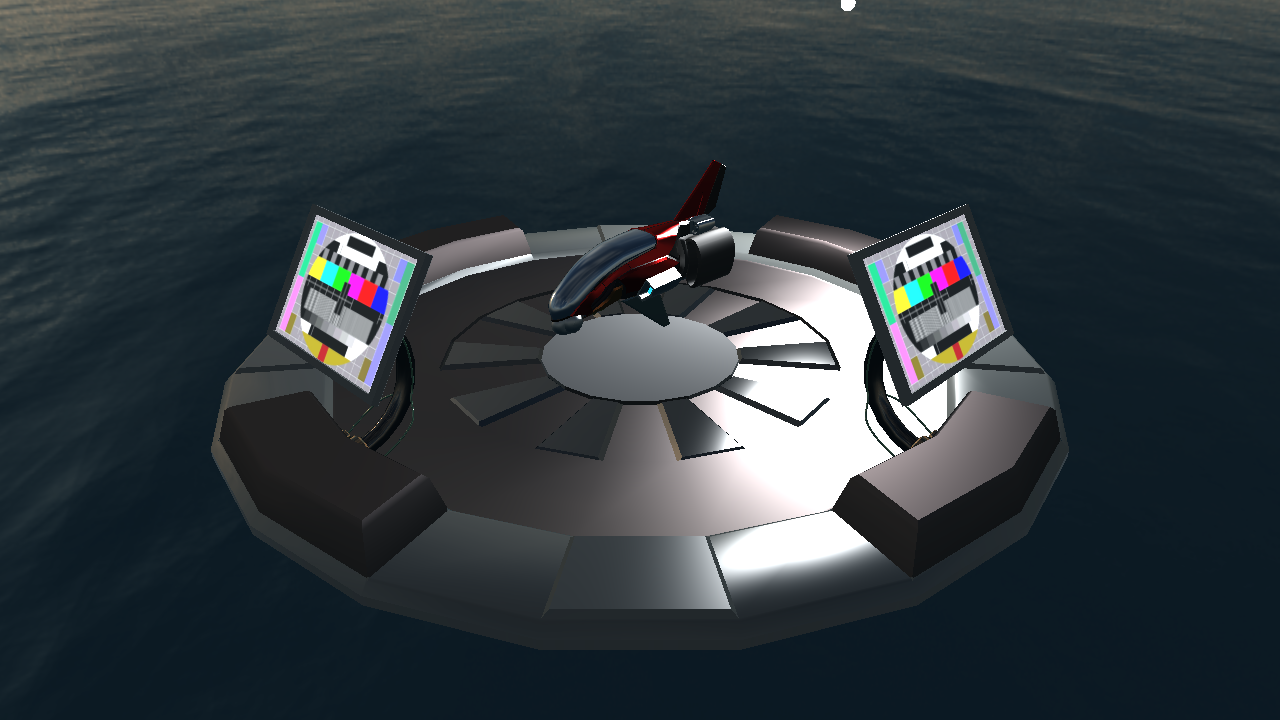
We have now rendered from the lights point of view. We can visualize this on the screens in a similar way as in the previous tutorial, by changing the texture id for the emissive texture of the screen:
labhelper::Material &screen = landingpadModel->m_materials[8];
screen.m_emission_texture.gl_id = shadowMapFB.colorTextureTarget;
And the result looks like the image below:

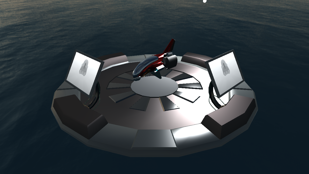
Now, instead of using the material color as the shading, let's make a gray-scale image corresponding to the depth. Change the out color of the fragment shader simple.frag to:
fragmentColor = vec4(gl_FragCoord.z);
gl_FragCoord is a built-in variable in glsl, and the z-component is the depth stored in the depth map. When we visualize the depth (throught the color texture) it should now look like below.
Click here to see solution (But try yourself first! You have to understand each step.)
Using the shadow map
Now that we have a shadow map, we probably want to use it. Basically, each time a fragment is drawn, we need to compare that fragments depth to a corresponding value in the shadow map. If the current fragment is further from the light than the value in the shadow map, it's in shadow. Otherwise, it's lit.
To find the corresponding value in the shadow map, we need to transform a coordinate from the camera's view-space to the shadow map's texture space. This involves a couple of matrices:
mat4 lightMatrix = translate(vec3(0.5f)) * scale(vec3(0.5f)) * lightProjectionMatrix * lightViewMatrix * inverse(viewMatrix);
labhelper::setUniformSlow(currentShaderProgram, "lightMatrix", lightMatrix);
Study the above matrix carefully. First, inverse(viewMatrix) transforms from (camera) view space to world space; next lightViewMatrix transforms from world space to light view space; and finally, lightProjectionMatrix transforms from light view space to light clip space. Thus, lightMatrix transforms a coordinate from camera view space to light clip space.
After these transformations, shadowMapCoord is in light clip space. Light clip space has coordinates in the range (-1, -1, -1) to (+1, +1, +1). However, texture coordinates run from (0, 0) to (1, 1). The depth value we've stored in our shadow map has the same range, i.e. between 0 and 1. So, it's convenient to rescale our coordinates here. That's what the translate() and scale() matrices are there for, they remap from clip space to texture-coordinates space.
We'll use the lightMatrix in the fragment shader (shading.frag), where we'll perform the transformation:
vec4 shadowMapCoord = lightMatrix * vec4(viewSpacePosition, 1.f);
Don't forget to declare the uniform:
uniform mat4 lightMatrix;
Time to implement the actual shadow map lookup. This we do in the fragment shader (shading.frag). First, make sure that you have declared the necessary inputs and uniforms:
in vec4 shadowMapCoord;
layout(binding = 10) uniform sampler2D shadowMapTex;
Next, we need to sample the depth value from the shadow map at the correct location. Then, we compare the depth value from the shadow map with the fragment's depth. If the depth from the shadow map is larger than the fragment's depth (i.e., the fragment is closer), then the fragment is lit. Otherwise, it's shadowed.
To do this, compute the visibility with the following code:
float depth = texture(shadowMapTex, shadowMapCoord.xy / shadowMapCoord.w).x;
float visibility = (depth >= (shadowMapCoord.z / shadowMapCoord.w)) ? 1.0 : 0.0;
Before we can see the results of our (hard) work, we need to bind the shadow map to texture unit 10 so that it can be accessed in our shaders. Add before the draw call in drawScene():
glActiveTexture(GL_TEXTURE10);
glBindTexture(GL_TEXTURE_2D, shadowMapFB.depthBuffer);
Now, run the program. It should look like something in the image below. There are some shadows, but we can also see some things that aren't quite right.

For one, there are some rather ugly patterns on the floor. The effect you're seeing is commonly referred to as "surface acne", and it's one of the problems that shadow maps commonly have. The following happens: A fragment on the floor that is not in shadow, looks up the corresponding depth in the shadow map. That depth is almost the same as the fragment's depth (ideally, it would be the same!). So sometimes our comparison will return that the fragment is closer and sometimes that it's further than the depth from the shadow map. The problem is discussed in the course book; especially look for Figure 9.17 there.
Secondly, you should see a completely black region outside the field-of-view that we render from the light source (on the farther side), and we haven't really tried to handle the case where we try to sample outside of the shadow map.
Click here to see solution (But try yourself first! You have to understand each step.)
Fixing the problems
To easier spot the artifacts on some screens, it may be easier if you increase the point_light_intensity_multiplier. To be able to switch back-and-forth to see the effect of different solutions, there are a few parameters that are controllable by the gui that you can use. You can toggle gui visibility by pressing G (you can also comment out the if surrounding the call to gui() in main()). You will play with a few parameters to see the effect of the steps to follow.
Shadow Acne
There are a couple of ways to 'fix' the first problem, surface acne. A simple (but far from perfect) way to do this is to simply "push" the polygons a tiny bit away from the light source when drawing the shadow map. In fact, OpenGL has some built-in functionality to help us with this. Before the rendering of the shadow map, add:
if (usePolygonOffset) {
    glEnable(GL_POLYGON_OFFSET_FILL);
    glPolygonOffset(polygonOffset_factor, polygonOffset_units);
}
After rendering the shadow map, and before we render from the cameras point-of-view, disable the polygon offset again:
if (usePolygonOffset) {
    glDisable(GL_POLYGON_OFFSET_FILL);
}
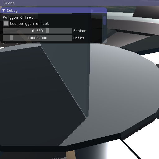
Tune the values polygon offset with the sliders until you do not see the acne.
Note: The units value is multiplied by a very small factor, so you will only see a difference when it has values in the order of thousands or tens of thousands.
Use a good set of values that you find when the application starts by initialising the polygon offset variables at their declaration in the code.
Play with the light position (specifically the zenith) to see how the different incident angles interact with the polygon offset factor and units.
Click here to see solution (But try yourself first! You have to understand each step.)
Peter-panning
Be mindful that too high values in the offset factor or offset units can lead to other kind of artifacts. For example, setting them to too high values leads to what is called Peter-Panning, in which the object looks to be floating above the surface, even though it's actually in contact with it.
Let's see that happening - select the scene called "Peter Panning" on the program's menu bar. That should bring up the following scene:
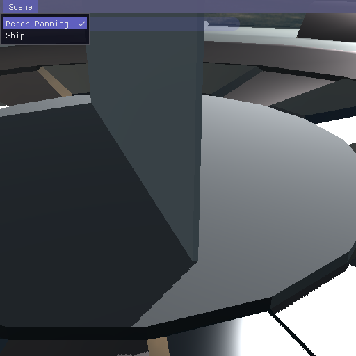
You can see that this is a very thin box that is resting on the ground of the landing pad.
Now, if you change the values to be way too high, as we do in the following image, you will see how it appears to float because the shadow appears to be too far away from the bottom of the object:
Click here to see solution (But try yourself first! You have to understand each step.)
Outside the shadow map
We start attacking the second problem by changing the clamping mode of the shadow map texture. By default, we got GL_CLAMP_TO_EDGE. So, when we sample outside of the shadow map, the shadow map lookup returns the value of the texel closest to the requested point. In this case, that's not a very useful value.
Let's control the clamp mode in display() after we have resized the shadowMapFB:
if (shadowMapClampMode == ClampMode::Edge) {
    glBindTexture(GL_TEXTURE_2D, shadowMapFB.depthBuffer);
    glTexParameteri(GL_TEXTURE_2D, GL_TEXTURE_WRAP_S, GL_CLAMP_TO_EDGE);
    glTexParameteri(GL_TEXTURE_2D, GL_TEXTURE_WRAP_T, GL_CLAMP_TO_EDGE);
}

if (shadowMapClampMode == ClampMode::Border) {
    glBindTexture(GL_TEXTURE_2D, shadowMapFB.depthBuffer);
    glTexParameteri(GL_TEXTURE_2D, GL_TEXTURE_WRAP_S, GL_CLAMP_TO_BORDER);
    glTexParameteri(GL_TEXTURE_2D, GL_TEXTURE_WRAP_T, GL_CLAMP_TO_BORDER);
    vec4 border(shadowMapClampBorderShadowed ? 0.f : 1.f);
    glTexParameterfv(GL_TEXTURE_2D, GL_TEXTURE_BORDER_COLOR, &border.x);
}

// This line is to avoid some warnings from OpenGL for having the shadowmap attached to texture unit 0
// when using a shader that samples from that texture with a sampler2D instead of a shadow sampler.
// It is never actually sampled, but just having it set there generates the warning in some systems.
glBindTexture(GL_TEXTURE_2D, 0);
Now, whenever we attempt to sample outside of the shadow map, our lookup returns 0.0. This causes any fragments that ask for such values to be in shadow or light, depending on the value that's set to border.
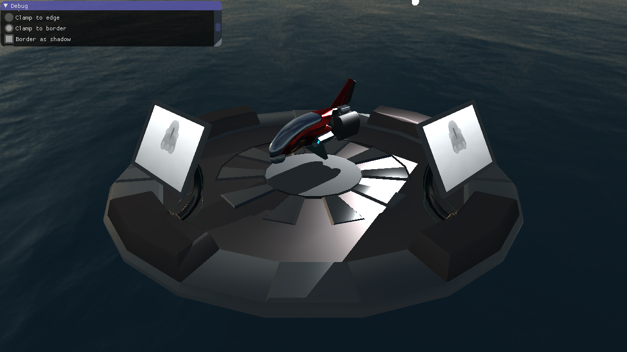
Run the program. When the border of the shadowmap is treated as if no shadow whas there the scene seems to look mostly okay, but that's because the shadowmap covers most of the visible scene. You can change this behaviour in the GUI by disabling Border as shadow. Do that and check that the scene now looks similar to the image below.
Now you can see there's still an unshadowed stripe where there shouldn't be one, and all in all, the hard rectangular shadow border doesn't look too good.
Our fundamental problem now is that we are rendering a single, rather directional shadow map. But, currently, our light is omni-directional. For this lab, we'll fix this by turning our light into a directional spot light. (The other option would be to extend the shadow map to be omni-directional, by e.g., turning it into a shadow cube map.)
Click here to see solution (But try yourself first! You have to understand each step.)
Use a spot light
A spot light only casts light inside a limited cone. That cone is defined by a direction (the light's direction) and an angle. To see whether a fragment is lit by a spot light, we need to compute the angle between the vector connecting the light to the fragment and the lights direction. This angle we then compare to the spot light's cone's opening angle.
In the fragment shader (shading.frag), add the following code:
vec3 posToLight = normalize(viewSpaceLightPosition - viewSpacePosition);
float cosAngle = dot(posToLight, -viewSpaceLightDir);

// Spotlight with hard border:
float spotAttenuation = (cosAngle > spotOuterAngle) ? 1.0 : 0.0;
visibility *= spotAttenuation;
Declare the necessary uniforms:
uniform vec3 viewSpaceLightDir;
uniform float spotOuterAngle;
We need to set values for these uniforms in drawScene(). Run the program. You should something like the picture shown below, to the left. The hard border isn't that nice - we'd prefer a soft transition like in the image to the right.
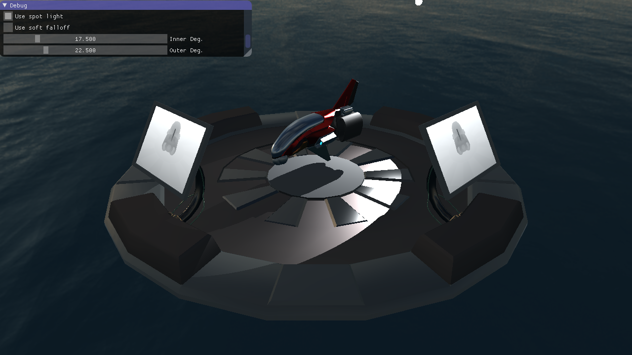
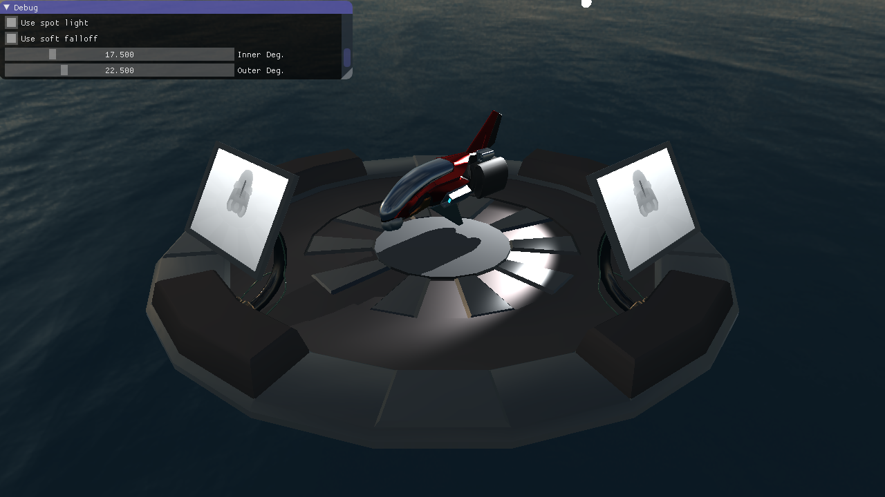
This is achieved by defining two angles, the inner and the outer angle. Everything outside of the outer angle is never lit by the spot light; everything inside the inner angle is potentially lit fully. For samples between those two angles, we'd like to smoothly interpolate, which gives us the nice soft and fuzzy transition shown above.
For the interpolation, we'll use the GLSL built-in function smoothstep(). The function takes three arguments, a lower bound, an upper bound, and a value. If the value is outside of the lower bound, smoothstep() returns zero. If the value is outside of the upper bound, smoothstep() returns one. Otherwise, it returns an smoothly varying value between zero and one. Check the GLSL documentation for a more exact definition!
Anyway, in the fragment shader change the following:
//float spotAttenuation = (cosAngle > spotOuterAngle) ? 1.0 : 0.0;
float spotAttenuation = smoothstep(spotOuterAngle, spotInnerAngle, cosAngle);
You'll need to declare spotInnerAngle as a uniform, similarly as we declared spotOuterAngle, and set its value in drawScene(). At this point you should know how to do this, so you get to do this by yourself.
Find appropriate values for the inner and outer angle -- try to maximize the spot light's "size", but avoid making the hard borders from the shadow map visible.
Click here to see solution (But try yourself first! You have to understand each step.)
Other types of lights
We have created a shadow for a spotlight by using a perspective projection when rendering the shadowmap.
How would you implement something similar but for the sun, where the rays can be considered to be parallel everywhere accross the scene, instead of converging to a point?
How about having a point light with shadows all around?
Hardware Support and other improvements
Now that we've fixed the most glaring issues with our shadow map, let's instead focus on some improvements.
Calculating shadow coords in the vertex shader
In task 2 we added code to the fragment shader to calculate the texture coordinates with the light matrix. This could be done in the vertex shader, which would reduce a bit the number of operations per fragment.
To do that, you need to move the uniform declaration you added in shading.frag for the light matrix to the vertex shader, shading.vert. You also need to declare an output variable in the vertex shader, and its corresponding input in the fragment shader:
out vec4 shadowMapCoord;
and in the fragment
in vec4 shadowMapCoord;
Click here to see solution (But try yourself first! You have to understand each step.)
Hardware shadow map lookup
Shadow mapping is common enough to warrant special support from OpenGL, and potentially from our GPU hardware. Right now, we fetch the depth from the shadow map and then perform the comparison manually. However, there are built-in functions that can help you with this in OpenGL and GLSL. Let's use these!
First, we need to change the way we set up our shadow map. In initGL() add the following lines for texture parameters for our shadow map:
glBindTexture(GL_TEXTURE_2D, shadowMapFB.depthBuffer);
glTexParameteri(GL_TEXTURE_2D, GL_TEXTURE_COMPARE_FUNC, GL_LEQUAL);
glTexParameteri(GL_TEXTURE_2D, GL_TEXTURE_COMPARE_MODE, GL_COMPARE_REF_TO_TEXTURE);
In the fragment shader, we need to do a few small adjustments too. First, we need to change the type of texture sampler we're going to use:
//layout(binding = 10) uniform sampler2D shadowMapTex;
layout(binding = 10) uniform sampler2DShadow shadowMapTex;
Next, instead of fetching a value with texture(), we're going to use (an overload of) textureProj():
//float depth= texture(shadowMapTex, shadowMapCoord.xy/shadowMapCoord.w).r;
//float visibility= (depth>=(shadowMapCoord.z/shadowMapCoord.w)) ? 1.0 : 0.0;
float visibility = textureProj(shadowMapTex, shadowMapCoord);
Visit the following two links for documentation on the changes that we've introduced:
- https://www.opengl.org/sdk/docs/man/html/glTexParameter.xhtml
- https://www.opengl.org/sdk/docs/man/html/textureProj.xhtml
First, identify the relevant sections in the documentation (e.g., which overload of textureProj did we use? Hint: look at the types of the function arguments.). Next, make sure you understand what each of the above changes is doing - you might be asked to explain this when you present your results to the assistants.
Click here to see solution (But try yourself first! You have to understand each step.)
Percentage Closer Filtering
First, make the shadow map smaller. For instance, 128 x 128 is a good choice for this. Run the program. You shadows should now look blocky and bad. Since this ain't Minecraft, we'd like to avoid such things and instead aim for a smooth look.
Percentage Closer Filter (PCF) will reduce this problem somewhat with very few changes. PCF is also supported by most hardware these days, so enabling it is quite cheap.
Change the texture filtering mode for the shadow map to GL_LINEAR (from GL_NEAREST set in the FboInfo class), and run the program again. Make sure it looks similar to the image below. If necessary, zoom in and look at the shadows close up to see the PCF in action.

Normally, interpolating depth values doesn't make much sense. So, something magic happens when you enable GL_LINEAR on a texture in combination with a GL_TEXTURE_COMPARE_MODE set to GL_COMPARE_REF_TO_TEXTURE. These parameters are explained in Section 8.23.1 in the OpenGL 4.4 Specification https://www.opengl.org/registry/doc/glspec44.core.pdf.
Can you make sense of that? PCF is further described in RTR4, in Section 7.5 (page 247++), and at e.g. https://developer.nvidia.com/gpugems/GPUGems/gpugems_ch11.html
Read the section on PCF in the book and/or the link provided, to get an idea of what's going on.
Click here to see solution (But try yourself first! You have to understand each step.)
Why Percentage Closer Filtering
Why don't we just compare the reference against the interpolated depth?
GUI
Make sure all the GUI options work. If you haven't done so yet, you need to use the variables shadowMapClampMode, shadowMapClampBorderShadowed, useSpotLight, useSoftFalloff, innerSpotlightAngle, outerSpotlightAngle, and useHardwarePCF, where appropriate.