Introduction
Set Lab2 as the startup project and run it. You will see a single colored quad drawn on screen. Now, take a look at the code and you will notice two large differences from the previous lab.
Initial code

The quad is drawn as an indexed mesh. That means that instead of sending six vertices to the glDrawArrays function as in Tutorial 1, a vertex buffer object containing the four vertices of the quad is created, and a second buffer object containing indices into this list is sent to the glDrawElements function. What is the point of this?
3D Perspective Camera
In the previous lab we drew the triangles essentially in 2D. Now, the four vertices are defined in three dimensional space and a projection matrix is sent along to the vertex shader. The perspective matrix is created with the following code:
mat4 projectionMatrix = perspective(fovy, aspectRatio, nearPlane, farPlane);
What are each of these arguments for (draw a picture if it will help you explain)?

Field of view:
Aspect ratio:
Near plane:
Far plane:
Adding texture coordinates
This quad may not look like much yet, but with a little imagination it could be the floor in a corridor of some old Wolfenstein game, or the road in an awesome racing game. Let's pretend it is. In this lab, we are going to make the awesome road look better by mapping a texture map to it. The first thing we need to do is to give each vertex a texture coordinate (often called uv-coordinate). This is done the same way as giving a vertex a position or a color. For starters, we will simply map the corners of the texture map to the corners of the quad. Just below where the vertex positions are defined, below the comment '// Task 1', define the texture coordinates:
float texcoords[] = {
	0.0f, 0.0f, // (u,v) for v0
	0.0f, 1.0f, // (u,v) for v1
	1.0f, 1.0f, // (u,v) for v2
	1.0f, 0.0f // (u,v) for v3
};
Next, we need to generate a buffer object containing this data, set up a vertex attribute pointer that points into that object, and enable that vertex attribute array. All of this will be done almost exactly as we do it for colors, so you will look at that code and do the same thing for texture coordinates.
First, we need to send these coordinates to the graphics board. Generate a buffer that will be used by OpenGL to store the texture coordinates.
Back in lab 1, the similar code we used for colors looked like this:
glGenBuffers(1, &colorBuffer);
glBindBuffer(GL_ARRAY_BUFFER, colorBuffer);
glBufferData(GL_ARRAY_BUFFER, labhelper::array_length(colors) * sizeof(float), colors, GL_STATIC_DRAW);
The variable colorBuffer (of type GLuint) is a number that identifies the buffer object. You will need a new number to identify the buffer object for texture coordinates. Don't forget to declare it together with the other buffer objects.
We will also need to access the texture coordinates in the vertex shader. For the colors, we attached the buffer to the vertex array object like this:
glVertexAttribPointer(1, 3, GL_FLOAT, false/*normalized*/, 0/*stride*/, 0/*offset*/);
Now do the same for the texture coordinates buffer object you just created. The first parameter tells that attribute with index 1 will get its values from colorBuffer. You want the attribute with index 2 to get its values from the texcoordBuffer. The second and third parameter tells that each element consists of three floats. The texture coordinates consist of two floats each.
Finally, we need to enable the new vertex attribute array. For colors, this was done with this line:
glEnableVertexAttribArray(1);
That's it! You have now added a buffer object containing texture coordinates to your vertex array object. We will use these to sample the texture later, but first, let us make sure they work.
First, we need to receive them in the vertex shader, so locate the line where the position input is declared in simple.vert:
layout(location = 0) in vec3 position;
and add a line for the incoming vertex attribute texCoordIn. Remember that the location must match the one used in the glVerteixAttribPointer call for the texture coordinates.
Next, we will just send this value along to the fragment shader. In the same way that we specified an outgoing color:
out vec3 color;
add the outgoing vec2 texCoord.
Similarly, in the fragment shader (simple.frag) the incoming color is defined as:
in vec3 outColor;
and you need to add texCoord as an incoming variable.
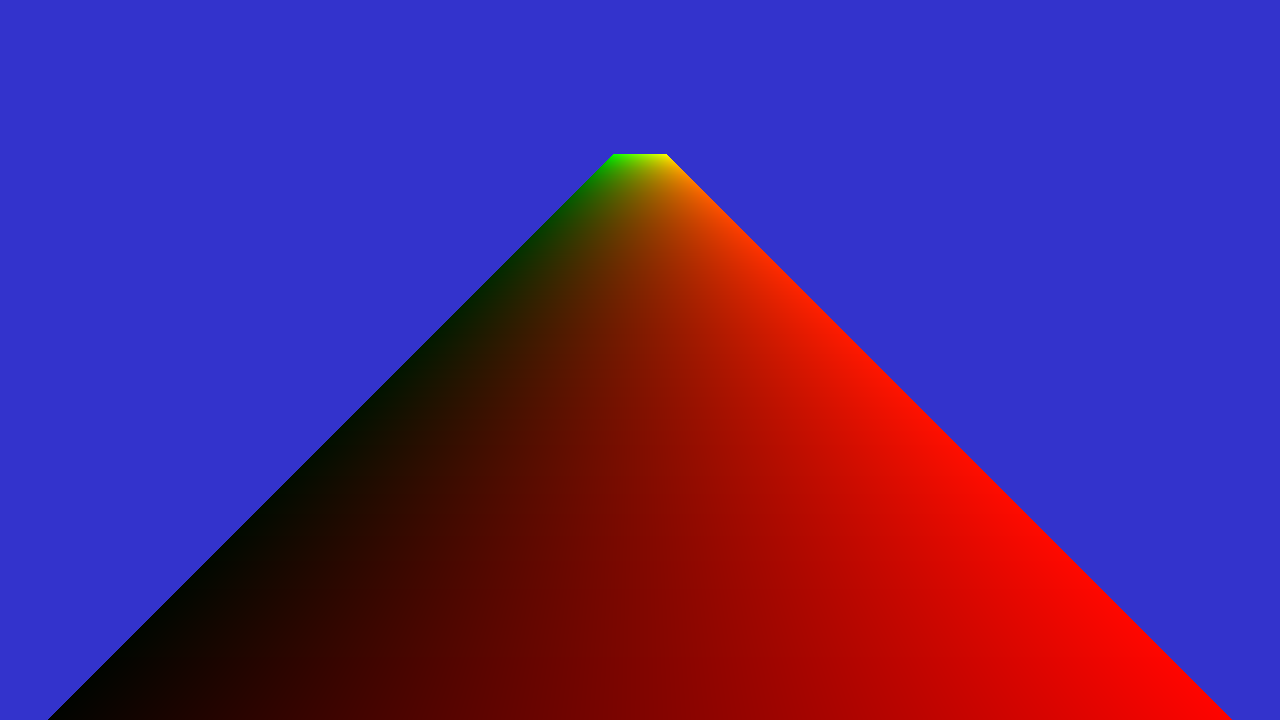
Now we can text that the texture coordinates work by pretending that they are colors and making sure we get the correct result. Change the fragment shader to be:
void main()
{
	fragmentColor = vec4(texCoord.x, texCoord.y, 0.0, 0.0);
}
And run the program. You should be able to "see" your texture coordinates like this:
Swizzling
Since accessing several parameters in a vector is very common in GLSL, these have some nice accessor names that are very useful to understand.
A vec4 has the members x, y, z, w, stored in this order. It also has aliases to these names, used to differentiate when a vector is used as a color or for texture coordinates: r, g, b, a and s, t, p, q. That means that a.x == a.r == a.s, and the same for the rest of the values. Note, also, that in the code for these lectures we will never use the stpq names, using xy for texture coordinates instead, since we find it clearer to remember.
They also have "swizzling" accessors, that is, you can combine several member names to obtain a composite element: a.xy gives you a vec2 with the x and y component of a, a.xyz gives you a vec3, and you can also change their order or repeat them like a.zyxx to obtain the equivalent of vec4(a.z, a.y, a.x, a.x). You can also assign to these components, like a.xyz = vec3(1, 2, 3). (Note that you can't swizzle with names from different types, such as a.rgxy).
This means that the bit of code for the shader we gave you right above could be written as fragmentColor = vec4(texCoord.st, 0, 0);.
Click here to see solution (But try yourself first! You have to understand each step.)
Loading a texture
To read a texture image from a file, we use stb_image, which is a header-only library in the public domain for reading and writing many image formats. We can load a texture that is in the lab2 directory with the following lines:
// Task 2.1
int w, h, comp;
unsigned char* image = stbi_load("../scenes/textures/asphalt.jpg", &w, &h, &comp, STBI_rgb_alpha);
Then we can generate a OpenGL texture and initialize it with the texture data. Textures are identified by an integer in OpenGL, and we can generate such an identifier with:
glGenTextures(1, &texture);
Then we can bind this texture, allocate storage and upload the data:
glBindTexture(GL_TEXTURE_2D, texture);
glTexImage2D(GL_TEXTURE_2D, 0, GL_RGBA, w, h, 0, GL_RGBA, GL_UNSIGNED_BYTE, image);
free(image);
The texture has a coordinate system with (0, 0) in the lower left corner and (1, 1) in the upper right corner of the image. We can define where to sample when a coordinate is outside this range, and we start by specifying OpenGL to clamp the texture coordinate to this range.
glTexParameteri(GL_TEXTURE_2D, GL_TEXTURE_WRAP_S, GL_CLAMP_TO_EDGE);
glTexParameteri(GL_TEXTURE_2D, GL_TEXTURE_WRAP_T, GL_CLAMP_TO_EDGE);
We also have to set up texture filtering. We will talk more about that later. For now, just add the lines:
glTexParameteri(GL_TEXTURE_2D, GL_TEXTURE_MIN_FILTER, GL_NEAREST);
glTexParameteri(GL_TEXTURE_2D, GL_TEXTURE_MAG_FILTER, GL_NEAREST);
Remember: The filtering for a texture always needs to be set. Otherwise it might be set to some random value, or not display the texture at all.
Click here to see solution (But try yourself first! You have to understand each step.)
Sampling the texture in the shader program
In shaders, textures are sampled from a texture unit. To sample an specific texture, we need to bind it to a texture unit. Before our draw call in the display() function, we make sure to bind our texture (texture id in the varaiable texture to texture unit 0. Add the following call, just before draw call glDrawElements():
// Task 3.1
glActiveTexture(GL_TEXTURE0);
glBindTexture(GL_TEXTURE_2D, texture);
In the fragment shader (file simple.frag) add a so called sampler. I.e., inform that the shader will use a texture that is connected to texture unit 0. You do this by adding to the fragment shader:
// Task 3.4
layout(binding = 0) uniform sampler2D colortexture;
The layout qualifier 'binding' specifies which texture unit to sample from. Now we have both texture coordinates and the texture sampler and to perform the texture fetch, replace the line that sets fragment color as:
// Task 3.5
fragmentColor = texture2D(colortexture, texCoord.xy);
Now run the program again and enjoy the textured highway:
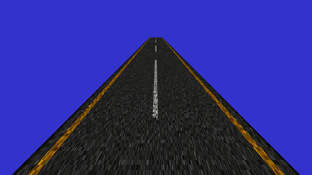
Click here to see solution (But try yourself first! You have to understand each step.)
Repeating the texture
Not as awesome as you hoped? Stretching a single road tile over the whole road is not exactly what we wanted is it? The floor is much longer than it is wide (20 units wide and 300 units long to be exact) but we map the square texture one-to-one on the quad, so the texture will be very stretched out. Instead, lets repeat the texture several times in the z-direction. Change the texture coordinates from task 1.1 as follows:
float texcoords[] = {
	0.0f, 0.0f,    // (u,v) for v0
	0.0f, 15.0f,   // (u,v) for v1
	1.0f, 15.0f,   // (u,v) for v2
	1.0f, 0.0f     // (u,v) for v3
};
Now run the program.
Apparently, we need to tell OpenGL what to do with texture coordinates outside the (0,1) range. Replace the texture parameters from task 2.1 (just after loading the texture) with the following parameters:
// Indicates that the active texture should be repeated,
// instead of for instance clamped, for texture coordinates > 1 or <-1.
glTexParameteri(GL_TEXTURE_2D, GL_TEXTURE_WRAP_S, GL_REPEAT);
glTexParameteri(GL_TEXTURE_2D, GL_TEXTURE_WRAP_T, GL_REPEAT);
This specifies that the coordinat will be treated as if the integer part is zero, meaning that coordinats (0, 0.3) and (0, 1.3) actually sample the same location in the texture, and the texture is effectively repeated along the road. Run the program again.

Click here to see solution (But try yourself first! You have to understand each step.)
Texture filtering
To improve the image we are now going to look at texture filtering. A problem we have run into is that parts of the texture are being shrunk to a much smaller size than the original image. So, when fetching a color from the texture for a pixel, the texture coordinate could actually map to any texel in a large area on the texture, but it will simply pick the texel on the texture coordinate that the middle of the pixel maps to.
A simple way to improve the result is to use mipmapping. Replace your glTexParameter(..., GL_NEAREST) calls with:
glGenerateMipmap(GL_TEXTURE_2D);
// Sets the type of filtering to be used on magnifying and
// minifying the active texture. These are the nicest available options.
glTexParameteri(GL_TEXTURE_2D, GL_TEXTURE_MAG_FILTER, GL_LINEAR);
glTexParameteri(GL_TEXTURE_2D, GL_TEXTURE_MIN_FILTER, GL_LINEAR_MIPMAP_LINEAR);
The call to glGenerateMipmap() generates the mipmap levels on the bound textures. The following two lines tell OpenGL to use the mipmap when minimizing a texture and to do linear filtering when magnifying. Run the program again.
You will notice that the image is now a lot less noisy, but that its mostly a blur far away. Add this line as well:
glTexParameterf(GL_TEXTURE_2D, GL_TEXTURE_MAX_ANISOTROPY_EXT, 16.0f);
which enables an extension, not part of core OpenGL 4. Nevertheless, this extension is available on your machines (this and other extensions are listed in the OpenGL registry). It enables the nicest level of anisotropic filtering. (Note that glTexParameter sets state per texture object and does so for the currently bound texture -- in our case texture which is bound by the call to glBindTexture above.) What happens with the final image and why?
Click here to see solution (But try yourself first! You have to understand each step.)
GUI
To be able to get a feel for the difference between the various filtering methods, use ImGui to easily switch between them. You can show/hide the gui window by pressing G (you can also comment out the if surrounding the call to gui() in main()). A skeleton has been provided with radio buttons and a slider.
Now implement what should happen when you press the different buttons or drag the slider, it should correspond to the description already next to them. Hint: the radio buttons are just numbered from zero and up for magnification and minification respectively.
Note: You can write the values for the numeric fields with your keyboard instead of dragging by Ctrl+Click on the field. This will be useful in later labs.
Click here to see solution (But try yourself first! You have to understand each step.)
Transparency
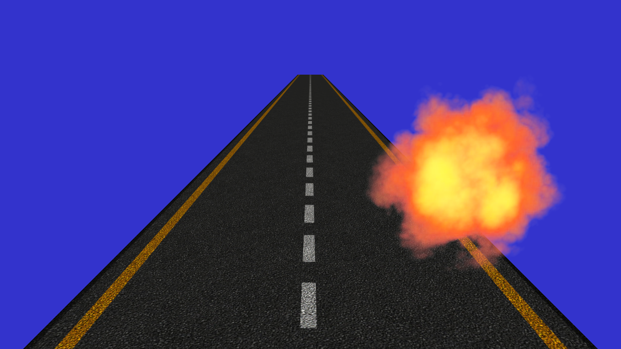
No game, no matter how fake, is complete without an explosion. We will create one by drawing a new quad and texture it with a picture of an explosion.
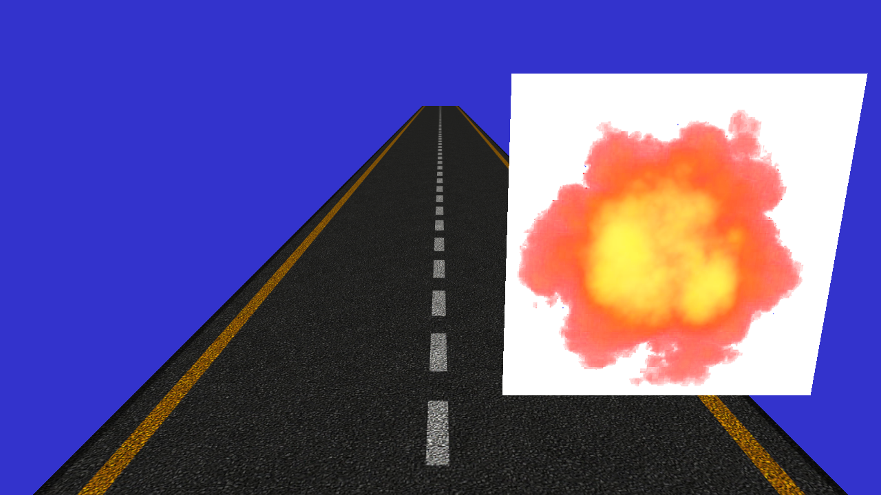
Create a new vertex array with data for positions and texture coordinates so it looks something like the image above. Also, load a new texture ("scenes/textures/explosion.png") and use it when drawing this new quad.
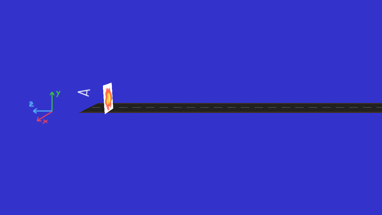
For reference, in the image below there's a side-view of the scene, with the coordinate axes of the view-space (which we are currently using) added so it's more obvious what direction is what.
This new texture you have loaded has an alpha channel as well as color channels; the alpha channel simply says how opaque each texel is, but it's clearly not being used yet. To get the transparent effect, we will have to enable blending. Add the following lines in the function display() somewhere before the call to your second glDrawElements(). The first line enables blending. The second specifies how the blending should be done.
glEnable(GL_BLEND);
glBlendFunc(GL_SRC_ALPHA, GL_ONE_MINUS_SRC_ALPHA);
With these parameters, the destination will receive an interpolated color value of:
α*source color + (1- α)*destination color
which faithfully corresponds to the behavior of transparency.
Note that to get correct transparent behavior, all overlapping transparent objects/polygons should be rendered in back-to-front order. It is common to first render all non-transparent objects in any order, and then sort all transparent objects/polygons and render them last.
Now run the program again and enjoy the exciting scene.
Click here to see solution (But try yourself first! You have to understand each step.)
Filtering (again)
This was working before, wasn't it? check that changing the selected options in the GUI changes the filtering in the road texture. It might have broken in this last step.
Fix it, and tell us what was the issue! If it didn't break for you, what do you think you have done that prevented it from happening?
Back-face Culling
GPUs have several optimisations to avoid rendering things that are not visible. For example, depth culling avoids executing fragment shaders for fragments that are covered by objects closer to the camera, and in this case, back-face culling avoids rendering triangles that "look away" from the camera, since, for a solid object, there will always be some face of the object that looks towards the camera and is covering any face that looks away.
To determine whether a face looks towards the camera or not, the winding order of the triangle is used. By default, OpenGL considers a triangle to be front-facing (looking towards the camera) if the vertices are given in counter-clockwise order.

To simplify things for you, in this lab we disabled back-face culling. Go to the cpp code, and in the display function find the following line, and change the glDisable call for glEnable.
glDisable(GL_CULL_FACE); //glEnable(GL_CULL_FACE);
If you now run the program again, it's very possible that some (or all) of the triangles are no longer visible. Play a bit with the order the vertices are rendered for each triangle to find out how this works. This will help you in future labs, where back-face culling is enabled.