Department of Computer Science and Engineering
Chalmers University of Technology, 412 96 Gothenburg, Sweden
erikbor@chalmers.se
CHOICE represents a VHDL code base which can be used to digitally emulate
a fiber-optic communication channel, on an FPGA or ASIC, according to the
Fiber-on-Chip (FoC) approach [1]. Emulation of DSP can significantly reduce
analysis runtimes of DSP implementations for which e.g. low bit-error rate
evaluations are needed. A CHOICE git repo containing FoC system components
is available at
https://www.cse.chalmers.se/~erikbor/choice/choice.git.
Contributors: Haorui Kan, Hong Zhou, Keren Liu.
Change Log
Date
Version
Content
2019-07-04
0.1
First version
2019-09-20
1.0
Added support for changing AWGN and phase noise scaling at run time.
2020-09-01
1.1
Rewrite of UART component for improved long-term stability
2021-01-10
1.2
Update of phase noise component scaling factor to support smaller linewidth symbol-duration products.
2022-03-07
2.0
Addition of PMD emulation and major updates to most components and examples.
2022-05-16
2.1
Increase resolution of cos and sin signals in pmd_rotation and pmd_phase to reduce fixed-point error.
Introduction
Verification and testing of complex digital signal processing (DSP) implementations
become time consuming as the implementations become more complex, especially for
designs where low bit-error rate (BER) data is needed. Such designs can be e.g.
forward error correction decoders or detection of cycle slips for carrier phase
recovery algorithms. The standard way of verifying an algorithm implemented in a
hardware description language (HDL) is through MATLAB-HDL co-simulation, where the
input data is generated in MATLAB, processed by a simulation of the HDL implementation
and imported back into MATLAB for post-processing. For low-BER simulations, the
runtime of these simulations can, however, easily become prohibitively long.
The Chalmers Optical Fiber Channel Emulator (CHOICE), originally presented in [2],
provides HDL code for FPGAs and ASICs with the purpose to create emulation systems
customized for fiber-optic communication and sensing systems. By digitally emulating
the fiber impairments using fixed-point representations for all signals, a
CHOICE-based FoC emulation systems can significantly reduce the runtime of low-BER
evaluations. The code in CHOICE enables the generation of long pseudo-random bitstreams,
their modulation and added digital fiber impairments in actual hardware. This emulation
can, in conjunction with running the DSP implementation on the same hardware, reduce
the DSP evaluation runtime by multiple orders of magnitude.
Currently, CHOICE consists of a pseudo-random bitstream generation component (rng),
a modulation component (modulator), an RRC filter (rrc), an additive white
Gaussian noise emulator (awgn), a phase noise emulator (phase_noise),
a PMD emulator (pmd, pmd_rotation, pmd_delay and pmd_phase),
a demodulator (demodulator), an error counter (error_counter) and a data
recorder (recorder). Currently all applicable components except the RRC filter and the
PMD emulator can be parallelized and the parallelism, i.e. the number of symbols processed
per clock cycle, is set by the PAR generic in each parallelizable component. The size of
each component is kept as small as possible to be able to test large DSP systems or to run
multiple instances of CHOICE simultaneously. Supplied with the package is also a UART
controller (uart) and several system examples. The latter can be found in the
src/examples folder. For the future, the plan is to develop the emulator further
by adding more fiber impairments and to further develop the analysis tools.
License
CHOICE is written by Erik Börjeson from the Department of Computer Science and Engineering
at Chalmers University of Technology and is released under version 3 of the GNU General
Public License (GPLv3).
We plan to describe CHOICE in more detail in a journal later in 2022, but for now, if you
use CHOICE in your work, please cite [2].
Cloning the Git Repo
The git repo can be cloned by doing git clone http://www.cse.chalmers.se/~erikbor/choice/choice.git
To also include the Gaussian noise generator (GNG) IP core used, do git clone --recurse http://www.cse.chalmers.se/~erikbor/choice/choice.git
More information about the GNG IP core can be found under the description of the AWGN component.
Components
This section describes the components of the CHOICE system and how to use them.
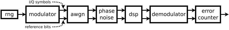
An example of how a single polarization CHOICE system can be implemented is shown
in Fig. 1. The binary data is generated in the rng component and fed to the
modulator component. AWGN and phase noise are added and symbols are fed to
the dsp unit under test. The output from the tested unit is demodulated and
the errors are counted. Each component takes both the modulated signal (i_in
and q_in) as well as the transmitted bits (bits_in) as inputs. The bits
are delayed to match the symbols so that the output of each block contains both the
symbols (i_out and q_out) and the matching transmitted bits
(bits_out). Valid signals (valid_in and valid_out) are used
to tell the next block in the chain when processing can begin.
An example of how a complete system can be implemented for a single polarization is
provided in src/examples/single/top.vhdl. This system include AWGN and phase
noise and utilizes UART communication to update the system parameters and to capture
the results. It uses an example DSP component (src/examples/single/dsp.vhdl)
that, for the purpose of a simple demonstration, adds a delay to the symbol stream.
The file describing the communication FSM (src/uart/communication.vhdl) outlines
the available UART commands. The 16-bit scaling factors for the AWGN and phase noise
parameters can be calculated using the Python scripts provided in the scripts folder.
Block diagram of an example system.
An example of a dual polarization system is provided in the src/examples/dual/top.vhdl
directory. This example utilizes the same components as the single polarization system, with
the addition of an RRC filter in the transmitter and PMD emulation in the channel. The RRC
filter upsamples the signal with a factor of 2, and thus all following components work on
two samples in parallel. The example DSP component provided in /src/examples/dual/dsp.vhdl
delays the symbols and provides basic downsampling by discarding every other sample. Settings
for the AWGN, phase noise and PMD can be updated over UART. The dual-polarization version is
currently not parallelizable.
Random Data Generation
Data generation is handled in the rng component using the Xorshift random number generation
(RNG) method described by Marsaglia [3]. The rng component works as a wrapper for the
xorshift component to generate the needed number of Xorshift RNGs. It also control the
generation of the valid_out signal. The periodicity of the pseudo-random bit sequence
is 264-1 for an Xorshift register wordlength (N) of 64. The rng component is
declared as
component rng is
generic (BITS : positive;
N : positive;
A : positive;
B : positive;
C : positive;
SEED : std_logic_vector);
port (clk : in std_logic;
rst : in std_logic;
bits_out : out std_logic_vector(BITS-1 downto 0);
valid_out : out std_logic);
end component rng;
Generics and their functions for the rng component.
Generic
Function
BITS
Number of bits to be generated each clock cycle.
N
Width of the register in the Xorshift RNGs.
A, B, C
Shift steps for the Xorshift RNGs, see [3] for suggested values.
SEED
Seed for the Xorshift RNGs, needs to have a wordlength of N·ceil(BITS/N).
Source files for the rng component.
Filename
Function
src/transmitter/rng.vhdl
Main rng component source.
src/transmitter/xorshift.vhdl
Subcomponent used to instantiate the Xorshift RNGs.
Modulation
Modulation of the bitstream generated in the rng is handled by the modulator component. Currently, these modulation formats are supported:
BPSK
QPSK
16QAM
64QAM
256QAM
The modulator component instantiates the chosen modulator and outputs a modulated I/Q signal. When using BPSK, the q_out signal can be ignored. A component declaration template is shown below.
component modulator is
generic (PAR : positive;
WIDTH : positive;
MOD_BITS : positive;
MOD_TYPE : string;
MAX_AMP : real);
port (clk : in std_logic;
rst : in std_logic;
bits_in : in std_logic_vector(PAR*MOD_BITS-1 downto 0);
valid_in : in std_logic;
i_out : out std_logic_vector(PAR*WIDTH-1 downto 0);
q_out : out std_logic_vector(PAR*WIDTH-1 downto 0);
bits_out : out std_logic_vector(PAR*MOD_BITS-1 downto 0);
valid_out : out std_logic);
end component modulator;
Generics and their functions for the modulator component.
Generic
Function
PAR
Parallelization factor of the modulator.
WIDTH
Wordlength of the modulated symbols.
MOD_BITS
Number of bits encoded on each symbol.
MOD_TYPE
Modulation format (BPSK, QPSK, 16QAM, 64QAM, 256QAM)
MAX_AMP
Fraction of the i_out and q_out signals to use for the symbol with the largest amplitude (0.0 - 1.0).
Source files for the modulator.
Filename
Function
src/transmitter/modulator.vhdl
Main modulator component source code.
src/transmitter/mod_BPSK.vhdl
Subcomponent for BPSK modulation.
src/transmitter/mod_QPSK.vhdl
Subcomponent for QPSK modulation.
src/transmitter/mod_16QAM.vhdl
Subcomponent for 16QAM modulation.
src/transmitter/mod_64QAM.vhdl
Subcomponent for 64QAM modulation.
src/transmitter/mod_256QAM.vhdl
Subcomponent for 256QAM modulation.
Additive White Gaussian Noise
The awgn component adds additive white Gaussian noise to
the input I/Q symbols. The component uses an Gaussian noise
generator IP core, written by Guangxi Liu, based on the
principle presented in [4]. The noise generator is available at
GitHub under
the GNU Lesser General Public License (LGPLv2.1).
The periodicity of the GNG is approximately 2175. If
you have already cloned the CHOICE repo and want to download
the GNG to the appropriate folder in the repo, do git
submodule init followed by git submodule update
in the CHOICE repo.
Seeds for the two GNG generators needed on each parallel lane for
the I and Q signals are taken from the awgn_pkg package, which
can be generated using the scripts/seeds.py script. Each GNG
instance needs three 64-bit vectors as seeds and the awgn is
designed to read different seeds from the package. The 16-bit scaling
input signal sets the noise level and can be calculated using
scripts/awgn_scaling.py. A component declaration of the awgn component is shown below.
component awgn is
generic (PAR : positive;
WIDTH : positive;
BITS : positive);
port (clk : in std_logic;
rst : in std_logic;
i_in : in std_logic_vector(PAR*WIDTH-1 downto 0);
q_in : in std_logic_vector(PAR*WIDTH-1 downto 0);
bits_in : in std_logic_vector(BITS-1 downto 0);
valid_in : in std_logic;
scaling : in std_logic_vector(15 downto 0);
i_out : out std_logic_vector(PAR*WIDTH-1 downto 0);
q_out : out std_logic_vector(PAR*WIDTH-1 downto 0);
bits_out : out std_logic_vector(BITS-1 downto 0);
valid_out : out std_logic);
end component awgn;
Generics and their functions for the awgn component.
Generic
Function
PAR
Parallelization factor.
WIDTH
Wordlength of the I/Q inputs and outputs.
BITS
Wordlength of the bits_in and bits_out ports.
Source files and IP for the awgn component.
Filename
Function
src/channel/awgn.vhdl
Main awgn component source code.
ip/gng/
Path to the Gaussian noise generator IP.
Phase Noise
CHOICE emulates the phase noise as a Weiner process, using the GNG IP core
described above to simulate the random walk. One GNG component is needed for
each parallel lane, and the seeds are fetched from the phase_noise_pkg
package. The package can be generated using the Python script scripts/seeds.py.
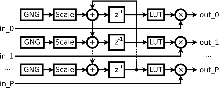
The parallelization of the phase_noise component is currently the
limiting factor for the parallelization of the complete single polarization
system. This limitation is due to the feedback loop present in the implementation,
shown in Fig. 2. The 16-bit scaling input signal sets the generated phase
noise and can be calculated using scripts/pn_scaling.py.
The component is designed to work both for the single and dual-polarization version.
For a single-polarization system, connect the I/Q and bits signals to the x
ports and map the y ports to open. An example of how this is done
is shown in src/examples/single/channel.vhdl. A component declaration
template for the phase_noise component is shown below.
component phase_noise is
generic (PAR : positive;
WIDTH : positive;
BITS : positive;
PHASE_WIDTH : positive;
LUT_WIDTH : positive);
port (clk : in std_logic;
rst : in std_logic;
x_i_in : in std_logic_vector(PAR*WIDTH-1 downto 0);
x_q_in : in std_logic_vector(PAR*WIDTH-1 downto 0);
y_i_in : in std_logic_vector(PAR*WIDTH-1 downto 0) := (others => '0');
y_q_in : in std_logic_vector(PAR*WIDTH-1 downto 0) := (others => '0');
bits_x_in : in std_logic_vector(BITS-1 downto 0);
bits_y_in : in std_logic_vector(BITS-1 downto 0) := (others => '0');
valid_in : in std_logic;
scaling : in std_logic_vector(15 downto 0);
x_i_out : out std_logic_vector(PAR*WIDTH-1 downto 0);
x_q_out : out std_logic_vector(PAR*WIDTH-1 downto 0);
y_i_out : out std_logic_vector(PAR*WIDTH-1 downto 0);
y_q_out : out std_logic_vector(PAR*WIDTH-1 downto 0);
bits_x_out : out std_logic_vector(BITS-1 downto 0);
bits_y_out : out std_logic_vector(BITS-1 downto 0);
valid_out : out std_logic);
end component phase_noise;
Block diagram of the phase noise generator component [2].
Generics and their functions for the phase noise emulator.
Generic
Function
PAR
Parallelization factor.
WIDTH
Wordlength of the I/Q inputs and outputs.
BITS
Wordlength of the bits_in and bits_out ports.
PHASE_WIDTH
Wordlength of the register storing the current phase rotation.
LUT_WIDTH
Wordlength of the LUT storing rotation vectors.
Source files and IP for the phase noise emulator
Filename
Function
src/channel/awgn.vhdl
Main awgn component source code.
src/channel/ang_to_iq.vhdl
Component used to convert an angle to an I/Q representation.
ip/gng/
Path to the Gaussian Noise Generator IP.
Polarization Mode Dispersion
Polarization mode dispersion is emulated using a waveplate model consisting of
a selectable number of fiber sections. The number of sections is controlled by
the SECTIONS_N generic, and the rotation angle (θ), phase shift (δ) and differential
group delay (DGD) can be controlled for each section separately. The emulator
includes the possibility to make the rotation angle time dependent, while the
other impairments are static. The emulation parameters can be controlled by setting
the corresponding input ports, which are strided std_logic_vectors.
The rightmost bits of these vectors describe the first PMD section. The PMD emulator
is based on the work done in [5] and is currently not parallelizable. A block diagram
and a component declaration template are shown below.
Block diagram of the PMD component.
component pmd is
generic (WIDTH : positive;
BITS : positive;
SECTIONS_N : positive;
THETA_WIDTH : positive;
COUNTER_WIDTH : positive;
TAP_WIDTH : positive;
TAPS_N : positive;
PHI_WIDTH : positive);
port (clk : in std_logic;
rst : in std_logic;
x_i_in : in std_logic_vector(2*WIDTH-1 downto 0);
x_q_in : in std_logic_vector(2*WIDTH-1 downto 0);
y_i_in : in std_logic_vector(2*WIDTH-1 downto 0);
y_q_in : in std_logic_vector(2*WIDTH-1 downto 0);
bits_x_in : in std_logic_vector(BITS-1 downto 0);
bits_y_in : in std_logic_vector(BITS-1 downto 0);
valid_in : in std_logic;
theta_start : in std_logic_vector((SECTIONS_N+1)*THETA_WIDTH-1 downto 0);
count_max : in std_logic_vector((SECTIONS_N+1)*COUNTER_WIDTH-1 downto 0);
direction : in std_logic_vector(SECTIONS_N downto 0);
taps : in std_logic_vector(TAPS_N*TAP_WIDTH-1 downto 0);
phi : in std_logic_vector(SECTIONS_N*PHI_WIDTH-1 downto 0);
x_i_out : out std_logic_vector(2*WIDTH-1 downto 0);
x_q_out : out std_logic_vector(2*WIDTH-1 downto 0);
y_i_out : out std_logic_vector(2*WIDTH-1 downto 0);
y_q_out : out std_logic_vector(2*WIDTH-1 downto 0);
bits_x_out : out std_logic_vector(BITS-1 downto 0);
bits_y_out : out std_logic_vector(BITS-1 downto 0);
valid_out : out std_logic);
end component pmd;
Generics and their functions for the PMD emulator.
Generic
Function
WIDTH
Wordlength of the I/Q inputs and outputs.
BITS
Wordlength of the bits_in and bits_out ports.
SECTIONS_N
Number of cocatenated fiber sections.
THETA_WIDTH
Wordlength of the PMD rotation parameter. The format is SII.FFF..., with valid values between -π and π.
COUNTER_WIDTH
Wordlength of the counter controlling the PMD rotation angle update.
TAP_WIDTH
Wordlength of the taps in the PMD DGD filter.
TAPS_N
Number of taps in the PMD DGD filter.
PHI_WIDTH
Wordlenth of the phase offset parameter. The format is SII.FFF..., with valid values between -π and π.
Source files and IP for the PMD emulator
Filename
Function
src/channel/pmd.vhdl
Main pmd component source code.
src/channel/pmd_rotation.vhdl
Sub-component source.
src/channel/pmd_delay.vhdl
Sub-component source
src/channel/pmd_phase.vhdl
Sub-component source
src/channel/theta_update.vhdl
Sub-component source
PMD Rotation
Polarization rotation is described by the Jones matrix [cos(θ) sin(θ); -sin(θ) cos(θ)],
where θ is the rotation angle. The theta signal uses a signed representation with
one sign bit, two integer bits and THETA_WIDTH-3 fractional bits. It has valid values
between -π and π.
component pmd_rotation is
generic (WIDTH : positive;
BITS : positive;
THETA_WIDTH : positive);
port (clk : in std_logic;
rst : in std_logic;
x_i_in : in std_logic_vector(2*WIDTH-1 downto 0);
x_q_in : in std_logic_vector(2*WIDTH-1 downto 0);
y_i_in : in std_logic_vector(2*WIDTH-1 downto 0);
y_q_in : in std_logic_vector(2*WIDTH-1 downto 0);
bits_x_in : in std_logic_vector(BITS-1 downto 0);
bits_y_in : in std_logic_vector(BITS-1 downto 0);
valid_in : in std_logic;
theta : in std_logic_vector(THETA_WIDTH-1 downto 0);
x_i_out : out std_logic_vector(2*WIDTH-1 downto 0);
x_q_out : out std_logic_vector(2*WIDTH-1 downto 0);
y_i_out : out std_logic_vector(2*WIDTH-1 downto 0);
y_q_out : out std_logic_vector(2*WIDTH-1 downto 0);
bits_x_out : out std_logic_vector(BITS-1 downto 0);
bits_y_out : out std_logic_vector(BITS-1 downto 0);
valid_out : out std_logic);
end component pmd_rotation;
Generics and their functions for the pmd_rotation component.
Generic
Function
WIDTH
Wordlength of the I/Q inputs and outputs.
BITS
Wordlength of the bits_in and bits_out ports.
THETA_WIDTH
Wordlength of the rotation angle. Format is SII.FFF...
Source files and IP for the pmd_rotation component
Filename
Function
src/channel/pmd_rotation.vhdl
Main pmd_rotation component source code.
PMD Delay
The pmd_delay component controls the differential group delay of each section
in the waveplate model. This is done using a Lagrange fractional delay filter.
The tap values can be calculated using the Python script provided in scripts/lagrange.py
and the tap input is a strided vector where the first tap is represented by the
TAP_WIDTH rightmost bits in the taps signal. An example component declaration
is shown below.
component pmd_delay is
generic (WIDTH : positive;
BITS : positive;
TAP_WIDTH : positive;
TAPS_N : positive);
port (clk : in std_logic;
rst : in std_logic;
x_i_in : in std_logic_vector(2*WIDTH-1 downto 0);
x_q_in : in std_logic_vector(2*WIDTH-1 downto 0);
y_i_in : in std_logic_vector(2*WIDTH-1 downto 0);
y_q_in : in std_logic_vector(2*WIDTH-1 downto 0);
bits_x_in : in std_logic_vector(BITS-1 downto 0);
bits_y_in : in std_logic_vector(BITS-1 downto 0);
valid_in : in std_logic;
taps : in std_logic_vector(TAPS_N*TAP_WIDTH-1 downto 0);
x_i_out : out std_logic_vector(2*WIDTH-1 downto 0);
x_q_out : out std_logic_vector(2*WIDTH-1 downto 0);
y_i_out : out std_logic_vector(2*WIDTH-1 downto 0);
y_q_out : out std_logic_vector(2*WIDTH-1 downto 0);
bits_x_out : out std_logic_vector(BITS-1 downto 0);
bits_y_out : out std_logic_vector(BITS-1 downto 0);
valid_out : out std_logic);
end component pmd_delay;
Generics and their functions for the pmd_delay component.
Generic
Function
WIDTH
Wordlength of the I/Q inputs and outputs.
BITS
Wordlength of the bits_in and bits_out ports.
TAP_WIDTH
Wordlength of the DGD filter taps.
TAPS_N
Number of filter taps.
Source files and IP for the pmd_delay component
Filename
Function
src/channel/pmd_delay.vhdl
Main pmd_delay component source code.
PMD Phase Shift
The pmd_phase components adds a constant phase offset to the I/Q signals of both
input polarizations. The offset is determined by the phi input, which uses a
signed representation with one sign bit, two integer bits and PHI_WIDTH-3 fractional bits.
This allows for phase offset values between -π and π.
component pmd_phase is
generic (WIDTH : positive;
BITS : positive;
PHI_WIDTH : positive);
port (clk : in std_logic;
rst : in std_logic;
x_i_in : in std_logic_vector(2*WIDTH-1 downto 0);
x_q_in : in std_logic_vector(2*WIDTH-1 downto 0);
y_i_in : in std_logic_vector(2*WIDTH-1 downto 0);
y_q_in : in std_logic_vector(2*WIDTH-1 downto 0);
bits_x_in : in std_logic_vector(BITS-1 downto 0);
bits_y_in : in std_logic_vector(BITS-1 downto 0);
valid_in : in std_logic;
phi : in std_logic_vector(PHI_WIDTH-1 downto 0);
x_i_out : out std_logic_vector(2*WIDTH-1 downto 0);
x_q_out : out std_logic_vector(2*WIDTH-1 downto 0);
y_i_out : out std_logic_vector(2*WIDTH-1 downto 0);
y_q_out : out std_logic_vector(2*WIDTH-1 downto 0);
bits_x_out : out std_logic_vector(BITS-1 downto 0);
bits_y_out : out std_logic_vector(BITS-1 downto 0);
valid_out : out std_logic);
end component pmd_phase;
Generics and their functions for the pmd_phase component.
Generic
Function
WIDTH
Wordlength of the I/Q inputs and outputs.
BITS
Wordlength of the bits_in and bits_out ports.
PHI_WIDTH
Wordlength of the rotation angle. Format is SII.FFF...
Source files and IP for the pnd_phase component
Filename
Function
src/channel/pmd_phase.vhdl
Main pmd_phase component source code.
Rotation Angle Update
The theta_update component is used to add a time-dependency to the PMD
rotation for each section. It's based around a COUNTER_WIDTH wide counter. Every
time count_max is reached, the value of the theta is increased/decreased
by one LSB, which means the speed of the PMD rotation can be controlled separately
for each section. The start port determines the start value of theta
and the direction port the direction of rotation, where '0' increases
theta and '1' decreases. If a constant PMD rotation is needed, set count_max
to zero. An example component declaration is shown below.
component theta_update is
generic (THETA_WIDTH : positive;
COUNTER_WIDTH : positive);
port (clk : in std_logic;
rst : in std_logic;
count_max : in std_logic_vector(COUNTER_WIDTH-1 downto 0);
start : in std_logic_vector(THETA_WIDTH-1 downto 0);
direction : in std_logic;
theta : out std_logic_vector(THETA_WIDTH-1 downto 0));
end component theta_update;
Generics and their functions for the theta_update component.
Generic
Function
THETA_WIDTH
Wordlength of the theta port.
COUNTER_WIDTH
Wordlength of the internal counter, controlling the minimum speed of the PMD rotation.
Source files and IP for the theta_update component
Filename
Function
src/channel/theta_update.vhdl
Main theta_update component source code.
Demodulation
Demodulation of the symbols is performed by the demodulator component, supporting the
same modulation formats as the modulation component. It instantiates the chosen
demodulator and outputs a demodulated bitstream. When using BPSK, the q_in input
signal can be connected to a constant. Shown below is an example component declaration of the demodulator.
component demodulator is
generic (PAR : positive;
WIDTH : positive;
MOD_BITS : positive;
MOD_TYPE : string;
MAX_AMP : real);
port (clk : in std_logic;
rst : in std_logic;
i_in : in std_logic_vector(PAR*WIDTH-1 downto 0);
q_in : in std_logic_vector(PAR*WIDTH-1 downto 0);
bits_in : in std_logic_vector(PAR*MOD_BITS-1 downto 0);
valid_in : in std_logic;
demod_out : out std_logic_vector(PAR*MOD_BITS-1 downto 0);
bits_out : out std_logic_vector(PAR*MOD_BITS-1 downto 0);
valid_out : out std_logic);
end component demodulator;
Generics and their function for the demodulator.
Generic
Function
PAR
Parallelization factor of the demodulator.
WIDTH
Wordlength of the modulated symbols.
MOD_BITS
Number of bits encoded on each symbol.
MOD_TYPE
Modulation format (BPSK, QPSK, 16QAM, 64QAM, 256QAM)
MAX_AMP
Fraction of the i_out and q_out signals to use for the symbol with the largest amplitude (0.0 - 1.0).
Source files for the demodulator.
Filename
Function
src/receiver/demodulator.vhdl
Main demodulator component source code.
src/receiver/demod_BPSK.vhdl
Subcomponent for BPSK demodulation.
src/receiver/demod_QPSK.vhdl
Subcomponent for QPSK demodulation.
src/receiver/demod_16QAM.vhdl
Subcomponent for 16QAM demodulation.
src/receiver/demod_64QAM.vhdl
Subcomponent for 64QAM demodulation.
src/receiver/demod_256QAM.vhdl
Subcomponent for 256QAM demodulation.
Error Counter
The output from the demodulator can be connected to the error_counter component.
This component counts the number of processed bits and the number of errors detected.
The output can be used to analyze the resulting BER. It can be read using a debugger
such as Xilinx ChipScope
or Intel Quartus SignalTap (pdf).
It can also be read from the FPGA using the UART controller provided with CHOICE (src/uart/uart.vhdl). See the
examples in src/examples for ways of implementing this functionality. The component is declared as shown below.
component error_counter is
generic (BITS : positive;
BITS_CNT_WIDTH : positive;
ERRORS_CNT_WIDTH : positive);
port (clk : in std_logic;
rst : in std_logic;
input0 : in std_logic_vector(BITS-1 downto 0);
input1 : in std_logic_vector(BITS-1 downto 0);
valid_in0 : in std_logic;
valid_in1 : in std_logic;
bits_cnt : out std_logic_vector(BITS_CNT_WIDTH-1 downto 0);
errors_cnt : out std_logic_vector(ERRORS_CNT_WIDTH-1 downto 0));
end component error_counter;
Generics and their function for the error counter.
Generic
Function
BITS
Wordlength of the bits_in input.
BITS_CNT_WIDTH
Wordlength of the bits counter, maximum value of the counter is 2BITS_CNT_WIDTH-1.
ERROR_CNT_WIDTH
Wordlength of the error counter, maximum value of the counter is 2ERROR_CNT_WIDTH-1.
Source files for the error counter.
Filename
Function
src/analysis/error_counter.vhdl
Main error_counter component source.
Data Recorder
Any signal inside the CHOICE environment can be captured using the recorder component.
On the rising edge of the clock, this component will store the present value of the data_in
port, if a trigger condition is met and the en signal is set. A trigger is detected
if the en and trig signals are set to 1 at a rising edge of the clock.
The done signal is set when the storage memory is full. To arm the recorder for a new
trigger the component needs to be reset. There are three modes of operation, set using the MODE generic:
The memory stores the DEPTH latest data samples received before a detected trigger event.
The memory will store DEPTH samples after a trigger event is detected.
A combination of the two previous modes, where DEPTH/2-1 samples are stored before and
DEPTH/2 samples are stored after a trigger event.
The captured data is read back on the data_out port by setting the addr signal
to the appropriate address. Address 0 always points to the oldest data sample, independent of the
MODE set. The recorder is optimized for Xilinx FPGAs, which will store the data in block RAMs.
entity recorder is
generic (WIDTH : positive;
DEPTH : positive;
MODE : natural range 0 to 2);
port (clk : in std_logic;
rst : in std_logic;
en : in std_logic;
data_in : in std_logic_vector(WIDTH-1 downto 0);
trig : in std_logic;
addr : in std_logic_vector(integer(ceil(log2(real(DEPTH))))-1 downto 0);
data_out : out std_logic_vector(WIDTH-1 downto 0);
done : out std_logic);
end entity recorder;
Generics and their function for the data recorder.
Generic
Function
WIDTH
Wordlength of the input data to capture.
DEPTH
Size of the storage memory, i.e. the number of samples to store.
MODE
Capture mode of the data recorder.
Source files for the data recorder.
Filename
Function
src/analysis/recorder.vhdl
Main recorder component source.
Development Boards
The emulator have been successfully implemented as a 22 nm ASIC design and on the following FPGA development boards:
[1] E. Börjeson and P. Larsson-Edefors,
"Fiber-on-Chip: Digital Emulation of Channel Impairments for Real-Time DSP Evaluation,"
IEEE Journal of Lightwave Technology, Early Access, Aug. 2022.
doi:10.1109/JLT.2022.3200248
[2] E. Börjeson, C. Fougstedt, and P. Larsson-Edefors,
"Towards FPGA Emulation of Fiber-Optic Channels for Deep-BER Evaluation of DSP Implementations,"
presented at Signal Processing in Photonic Communications (SPPCom), paper SpTh1E.4, San Francisco, CA, USA, Aug 2019.
doi:10.1364/SPPCOM.2019.SpTh1E.4
[3] G. Marsaglia,
"Xorshift RNGs,"
Journal of Statistical Software, vol. 8, no. 14, pp. 1-6, 2003.
[4] R. Gutierrez et al.,
"Hardware Architecture of a Gaussian Noise Generator Based on the Inversion Method,"
IEEE Transactions on Circuits and Systems II: Express Briefs, vol. 59, no. 8, pp. 501-505, Aug. 2012.
doi:10.1109/TCSII.2012.2204119
[5] H. Kan, H. Zhou, E. Börjeson, M. Karlsson, and P. Larsson-Edefors,
"Digital Emulation of Time-Varying PMD for Real-Time DSP Evaluations,"
presented at Asia Communications and Photonics Conference (ACP), paper M4H.4, Shanghai, China, Oct. 2021.