In this lab, we'll implement a technique called Shadow Mapping. Shadows greatly increase the realism of computer generated images, and shadow mapping is one of the most commonly used techniques to produce shadows in real time applications. The shadow map algorithm assumes a directional light or a point light source, and in this tutorial we will use a point light source.
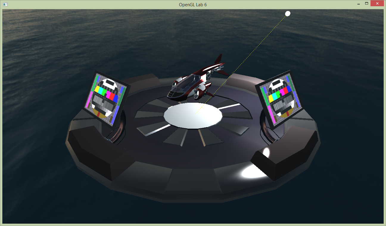
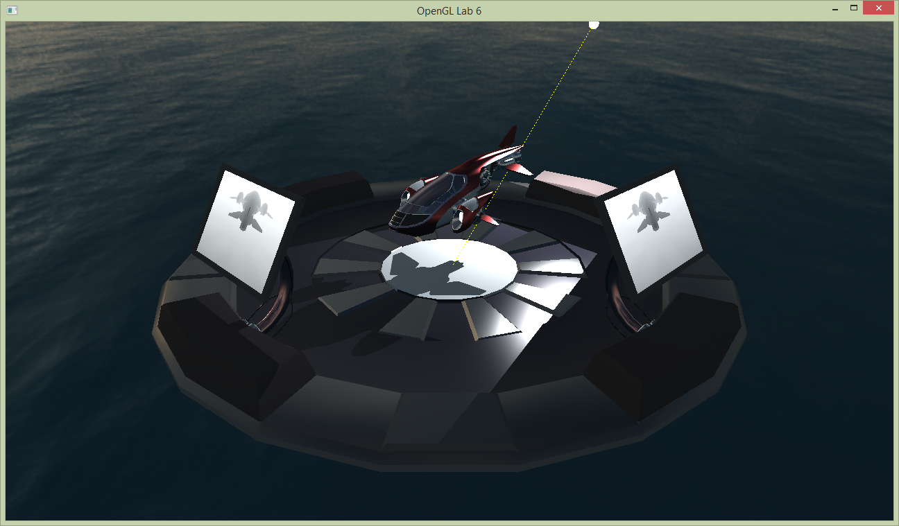
To start with this tutorial, run Lab 6. You will notice that the shading is not implemented yet. Re-use your implementation of calculateDirectIllumination() and calculateIndirectIllumination() from previous tutorials in shader.frag, and the result will look like below. There's a light source rotating around the space ship in the middle - but the shadows are missing! Let's fix that.
The basic idea of shadow mapping is to first render a depth-map from the lights point-of-view. The depth map contains the closest surfaces and are therefore lit. Surfaces that are further away are then in shadow. Secondly, we render from the cameras point-of-view. We then determine if a fragment is lit or in shadow by projecting it onto the image-plane of the shadow map, sample the shadow map (a depth) and check if the distance from the fragment to the light source is about the same as that of the lit surface.
For a more detailed explanation, see the section on shadow mapping in the course book (9.1.4), or the lecture slides. Look through the code and make sure you understand what it does. Especially note the view and projection matrices for the light source, since we will need those when rendering the shadow map. This is similar to the TV camera in the previous tutorial; if necessary, revisit that.
Task 1: Rendering depth
A shadow map is simply a texture containing a depth buffer rendered from the light's point of view. We'll need to do a render-to-texture pass to get this, much like the previous lab. Before we get there, we'll visualize the content of the depths of the shadow map as a gray scale image on the screens on the landing pad.
Have a look at display() and the variables of the light (the position, the view and projection matrices). We will use these when rendering from the light, but first we need to setup the parameters for the framebuffer. We have prepared a framebuffer to render to already: FboInfo shadowMapFB; is declared in the global scope. In display() (at task 1) we need to resize the framebuffer in case the width or height is not equal to the shadowMapResolution
// >>> @task 1
if (shadowMapFB.width != shadowMapResolution || shadowMapFB.height != shadowMapResolution) {
	shadowMapFB.resize(shadowMapResolution, shadowMapResolution);
}simpleShader shader program:
drawScene(simpleShaderProgram, lightViewMatrix, lightProjMatrix, lightViewMatrix, lightProjMatrix);We have now rendered from the lights point of view. We can visualize this on the screens in a similar way as in the previous tutorial, by changing the texture id for the emissive texture of the screen:
labhelper::Material &screen = landingpadModel->m_materials[8];
screen.m_emission_texture.gl_id = shadowMapFB.colorTextureTarget;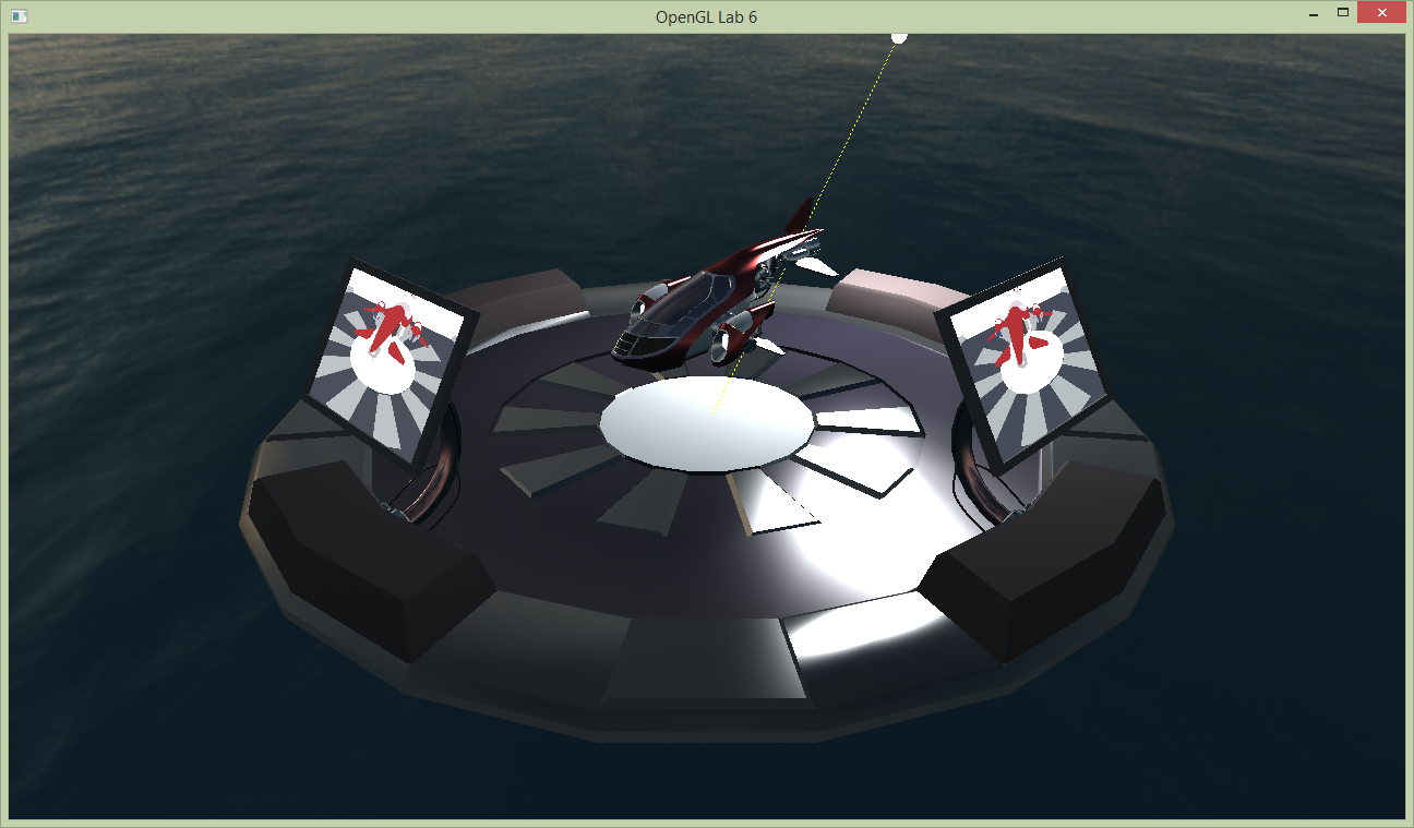
Now, instead of using the material color as the shading, let's make a gray-scale image corresponding to the depth. Change the out color of the fragment shader simple.frag to:
fragmentColor = vec4(gl_FragCoord.z);
gl_FragCoord is a built-in variable in glsl, and the z-component is the depth stored in the depth map. When we visualize the depth (throught the color texture) it should now look like below.
Task 2: Using the shadow map
Now that we have a shadow map, we probably want to use it. Basically, each time a fragment is drawn, we need to compare that fragments depth to a corresponding value in the shadow map. If the current fragment is further from the light than the value in the shadow map, it’s in shadow. Otherwise, it’s lit.
To find the corresponding value in the shadow map, we need to transform a coordinate from the camera’s view-space to the shadow map’s texture space. This involves a couple of matrices:
mat4 lightMatrix = lightProjectionMatrix * lightViewMatrix * inverse(viewMatrix);
labhelper::setUniformSlow(currentShaderProgram, "lightMatrix", lightMatrix);inverse(viewMatrix) transforms from (camera) view space to world space; next lightViewMatrix transforms from world space to light view space; and finally, lightProjectionMatrix transforms from light view space to light clip space. Thus, lightMatrix transforms a coordinate from camera view space to light clip space.
We’ll use the lightMatrix in the vertex shader (shading.vert), where we perform the transformation and send the result to the fragment shader:
shadowMapCoord = lightMatrix * vec4(viewSpacePosition, 1.0);uniform mat4 lightMatrix;
out vec4 shadowMapCoord;shadowMapCoord.xyz *= vec3(0.5, 0.5, 0.5);
shadowMapCoord.xyz += shadowMapCoord.w * vec3(0.5, 0.5, 0.5);shadowMapCoord.w will cancel out later when we divide by it.
Time to implement the actual shadow map lookup. This we do in the fragment shader (shading.frag). First, make sure that you have declared the necessary inputs and uniforms:
in vec4 shadowMapCoord;
layout(binding = 10) uniform sampler2D shadowMapTex;
To do this, compute the visibility with the following code:
float depth = texture(shadowMapTex, shadowMapCoord.xy / shadowMapCoord.w).x;
float visibility = (depth >= (shadowMapCoord.z / shadowMapCoord.w)) ? 1.0 : 0.0;glActiveTexture(GL_TEXTURE10);
glBindTexture(GL_TEXTURE_2D, shadowMapFB.depthBuffer);
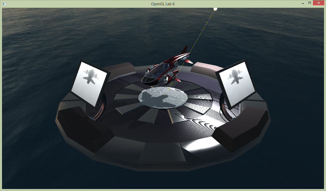
For one, there are some rather ugly patterns on the floor. The effect you’re seeing is commonly referred to as “surface acne”, and it’s one of the problems that shadow maps commonly have. The following happens: A fragment on the floor that is not in shadow, looks up the corresponding depth in the shadow map. That depth is almost the same as the fragment’s depth (ideally, it would be the same!). So sometimes our comparison will return that the fragment is closer and sometimes that it’s further than the depth from the shadow map. The problem is discussed in the course book; especially look for Figure 9.17 there.
Secondly, you should see a completely black region outside the field-of-view that we render from the light source (on the farther side), and we haven’t really tried to handle the case where we try to sample outside of the shadow map.
Task 3: Fixing the problems
To easier spot the artifacts on some screens, it may be easier if you increase the point_light_intensity_multiplier. To be able to switch back-and-forth to see the effect of different solutions, there are a few parameters that are controllable by the gui that you can use. To show the GUI, press g or just uncomment the if statement around the call to gui(); in the render loop in main(). You will play with a few parameters to see the effect of the steps to follow.
Task 3.1: Shadow Acne
There are a couple of ways to ‘fix’ the first problem, surface acne. A simple (but far from perfect) way to do this is to simply “push” the polygons a tiny bit away from the light source when drawing the shadow map. In fact, OpenGL has some built-in functionality to help us with this. Before the rendering of the shadow map, add:
if (usePolygonOffest) {
	glEnable(GL_POLYGON_OFFSET_FILL);
	glPolygonOffset(polygonOffset_factor, polygonOffset_units);
}
if (usePolygonOffest) {
	glDisable(GL_POLYGON_OFFSET_FILL);
}Task 3.2: Outside the shadow map
We start attacking the second problem by changing the clamping mode of the shadow map texture. By default, we got GL_CLAMP_TO_EDGE. So, when we sample outside of the shadow map, the shadow map lookup returns the value of the texel closest to the requested point. In this case, that’s not a very useful value.
Let's control the clamp mode in display() after we have resized the shadowMapFB:
if (shadowMapClampMode == ClampMode::Edge) {
	glBindTexture(GL_TEXTURE_2D, shadowMapFB.depthBuffer);
	glTexParameteri(GL_TEXTURE_2D, GL_TEXTURE_WRAP_S, GL_CLAMP_TO_EDGE);
	glTexParameteri(GL_TEXTURE_2D, GL_TEXTURE_WRAP_T, GL_CLAMP_TO_EDGE);
}

if (shadowMapClampMode == ClampMode::Border) {
	glBindTexture(GL_TEXTURE_2D, shadowMapFB.depthBuffer);
	glTexParameteri(GL_TEXTURE_2D, GL_TEXTURE_WRAP_S, GL_CLAMP_TO_BORDER);
	glTexParameteri(GL_TEXTURE_2D, GL_TEXTURE_WRAP_T, GL_CLAMP_TO_BORDER);
	vec4 zeros(0.0f);
	glTexParameterfv(GL_TEXTURE_2D, GL_TEXTURE_BORDER_COLOR, &zeros.x);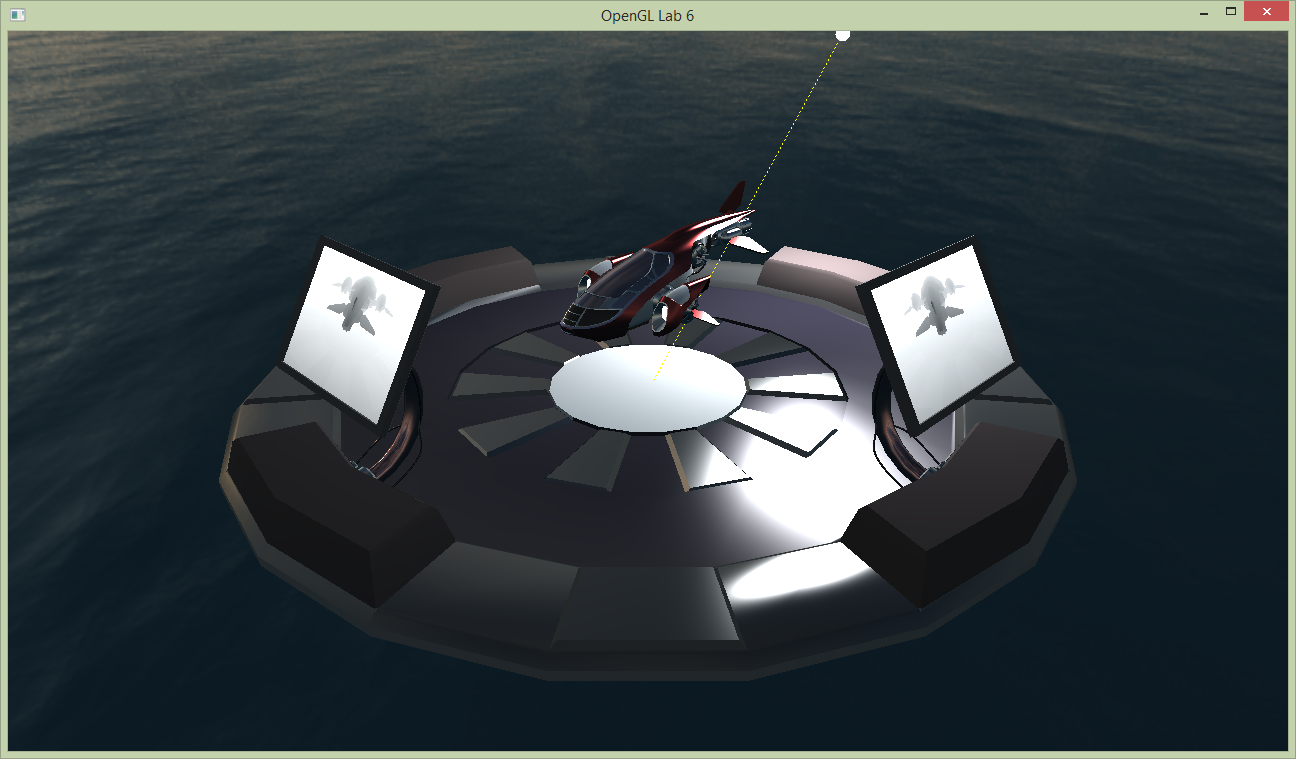
}Run the program and make sure it looks similar to the image below. There’s still an unshadowed stripe where there shouldn’t be one, and all in all, the hard rectangular shadow border doesn’t look too good.
Our fundamental problem is that we are rendering a single, rather directional shadow map. But, currently, our light is omni-directional. For this lab, we’ll fix this by turning our light into a directional spot light. (The other option would be to extend the shadow map to be omni-directional, by e.g., turning it into a shadow cube map.)
Task 3.3: Use a spot light
A spot light only casts light inside a limited cone. That cone is defined by a direction (the light’s direction) and an angle. To see whether a fragment is lit by a spot light, we need to compute the angle between the vector connecting the light to the fragment and the lights direction. This angle we then compare to the spot light’s cone’s opening angle.
In the fragment shader (shading.frag), add the following code:
vec3 posToLight = normalize(viewSpaceLightPosition - viewSpacePosition);
float cosAngle = dot(posToLight, -viewSpaceLightDir);

// Spotlight with hard border:
float spotAttenuation = (cosAngle > spotOuterAngle) ? 1.0 : 0.0;
visibility *= spotAttenuation;uniform vec3 viewSpaceLightDir;
uniform float spotOuterAngle;drawScene(). Run the program. You should something like the picture shown below, to the left. The hard border isn’t that nice - we’d prefer a soft transition like in the image to the right.
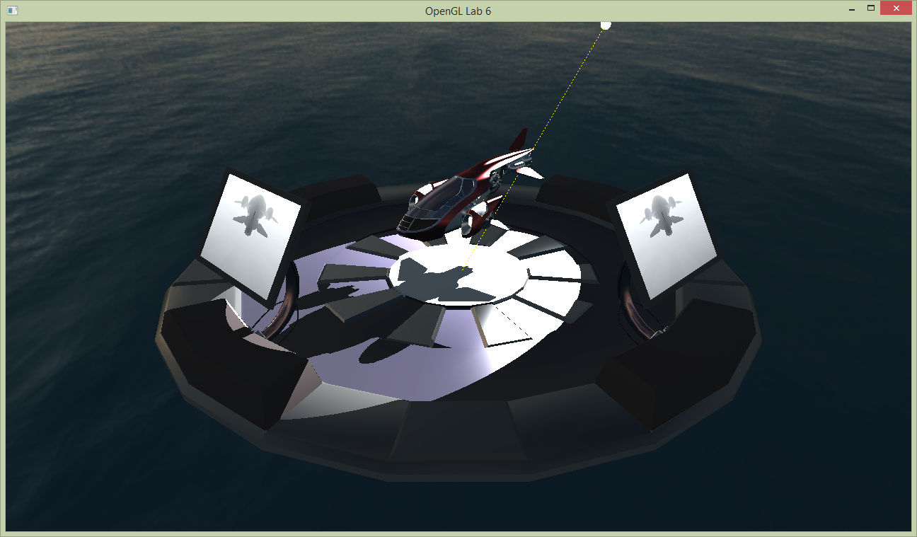
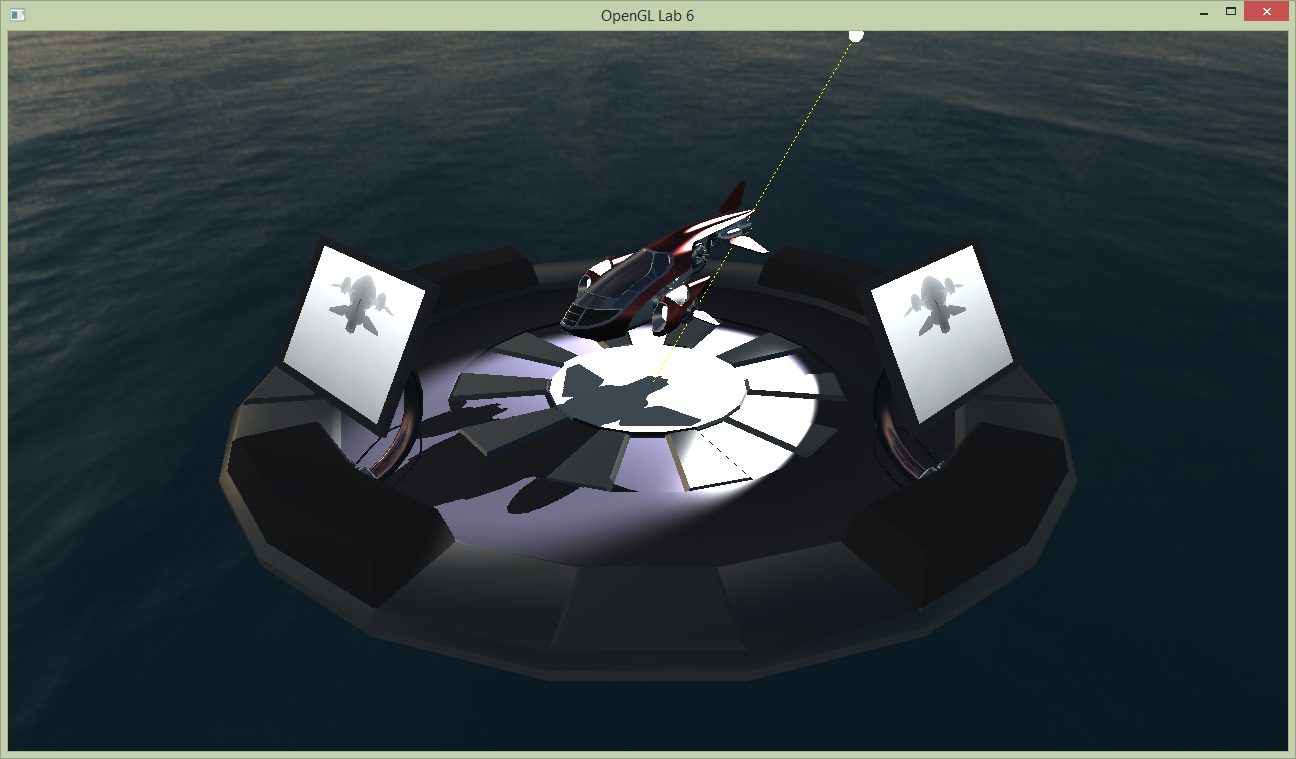
This is achieved by defining two angles, the inner and the outer angle. Everything outside of the outer angle is never lit by the spot light; everything inside the inner angle is potentially lit fully. For samples between those two angles, we’d like to smoothly interpolate, which gives us the nice soft and fuzzy transition shown above.
For the interpolation, we’ll use the GLSL built-in function smoothstep(). The function takes three arguments, a lower bound, an upper bound, and a value. If the value is outside of the lower bound, smoothstep() returns zero. If the value is outside of the upper bound, smoothstep() returns one. Otherwise, it returns an smoothly varying value between zero and one. Check the GLSL documentation for a more exact definition!
Anyway, in the fragment shader, change the following:
//float spotAttenuation = (cosAngle > spotOuterAngle) ? 1.0 : 0.0;
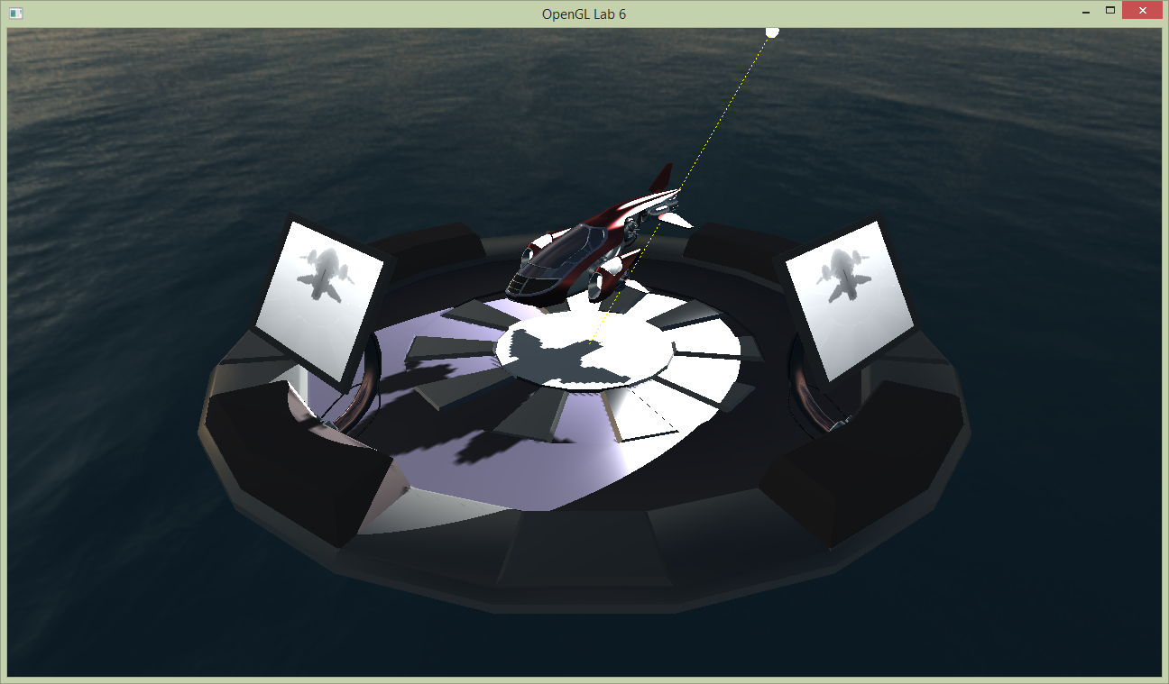
float spotAttenuation = smoothstep(spotOuterAngle, spotInnerAngle, cosAngle);You’ll need to declare spotInnerAngle as a uniform, and set its value in drawScene(). At this point, you should know how to do this, so you get to do this by yourself. Find appropriate values for the inner and outer angle – try to maximize the spot light’s “size”, but avoid making the hard borders from the shadow map visible.
Task 5: Hardware Support and other improvements
Now that we’ve fixed the most glaring issues with our shadow map, let’s instead focus on some improvements.
Re-scaling
Recall the vertex shader. We adjust the shadow map coordinates by scaling with 0.5 and translating with 0.5; we need to do this to transform the coordinates from their original (-1, 1)³ to (0, 1)³ range that we need for the computations in the fragment shader.
This transformation could easily be included in the lightMatrix. After all, a 4 by 4 matrix can represent scaling and translation.
Implement this in lab6_main.cpp, where you construct the lightMatrix. Then remove the old code from the vertex shader; your goal here is to reduce the vertex shader work to compute shadowMapCoord to a single matrix-vector multiplication.
Hint: Use the matrix construction functions scale() and translate().
Hardware shadow map lookup
Shadow mapping is common enough to warrant special support from OpenGL, and potentially from our GPU hardware. Right now, we fetch the depth from the shadow map and then perform the comparison manually. However, there are built-in functions that can help you with this in OpenGL and GLSL. Let’s use these!
First, we need to change the way we set up our shadow map. In initGL() add the following lines for texture parameters for our shadow map:
glBindTexture(GL_TEXTURE_2D, shadowMapFB.depthBuffer);
glTexParameteri(GL_TEXTURE_2D, GL_TEXTURE_COMPARE_FUNC, GL_LEQUAL);
glTexParameteri(GL_TEXTURE_2D, GL_TEXTURE_COMPARE_MODE, GL_COMPARE_REF_TO_TEXTURE);//layout(binding = 10) uniform sampler2D shadowMapTex;
layout(binding = 10) uniform sampler2DShadow shadowMapTex;//float depth= texture( shadowMapTex, shadowMapCoord.xy/shadowMapCoord.w ).r;
//float visibility= (depth>=(shadowMapCoord.z/shadowMapCoord.w)) ? 1.0 : 0.0;
float visibility = textureProj( shadowMapTex, shadowMapCoord );- https://www.opengl.org/sdk/docs/man/html/glTexParameter.xhtml
- https://www.opengl.org/sdk/docs/man/html/textureProj.xhtml
textureProj did we use? Hint: look at the types of the function arguments.). Next, make sure you understand what each of the above changes is doing - you might be asked to explain this when you present your results to the assistants.
Percentage Closer Filtering
First, make the shadow map smaller. For instance, 128 x 128 is a good choice for this. Run the program. You shadows should now look blocky and bad. Since this ain’t Minecraft, we’d like to avoid such things and instead aim for a smooth look.
Percentage Closer Filter (PCF) will reduce this problem somewhat with very few changes. PCF is also supported by most hardware these days, so enabling it is quite cheap.
Change the texture filtering mode for the shadow map to GL_LINEAR (from GL_NEAREST set in the FboInfo class), and run the program again. Make sure it looks similar to the image below. If necessary, zoom in and look at the shadows close up to see the PCF in action.
Normally, interpolating depth values doesn’t make much sense. So, something magic happens when you enable GL_LINEAR on a texture in combination with a GL_TEXTURE_COMPARE_MODE set to GL_COMPARE_REF_TO_TEXTURE. Read Section 8.23.1 in the OpenGL 4.4 Specification: