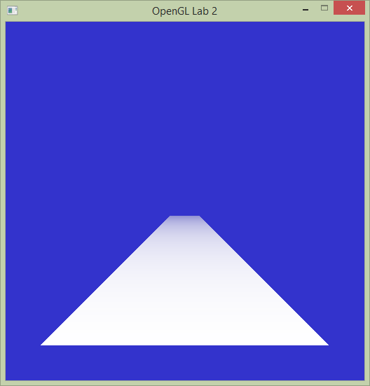
Set Lab2 as the startup project and run it. You will see a single colored quad drawn on screen. Now, take a look at the code and you will notice two large differences from the previous lab.
Exercise 1
 The quad is drawn as an indexed mesh. That means that instead of sending six vertices to the
 glDrawArrays function as in Tutorial 1, a vertex buffer object containing the four vertices of the quad is created, and a second buffer object containing indices into this list is sent to the glDrawElements function. What is the point of this?
Exercise 2
In the previous lab we drew the triangles essentially in 2D. Now, the four vertices are defined in three dimensional space and a projection matrix is sent along to the vertex shader. The perspective matrix is created with the following code:
mat4 projectionMatrix = perspective(fovy, aspectRatio, nearPlane, farPlane);
Task 1: Adding texture coordinates
This quad may not look like much yet, but with a little imagination it could be the floor in a corridor of some old Wolfenstein game, or the road in an awesome racing game. Let’s pretend it is. In this lab, we are going to make the awesome road look better by mapping a texture map to it. The first thing we need to do is to give each vertex a texture coordinate (often called uv-coordinate). This is done the same way as giving a vertex a position or a color. For starters, we will simply map the corners of the texture map to the corners of the quad. Just below where the vertex positions are defined, below the comment '// >>> @task 1', define the texture coordinates:
float texcoords[] = {
	0.0f, 0.0f, // (u,v) for v0
	0.0f, 1.0f, // (u,v) for v1
	1.0f, 1.0f, // (u,v) for v2
	1.0f, 0.0f // (u,v) for v3
};
Next, we need to generate a buffer object containing this data, set up a vertex attribute pointer that points into that object, and enable that vertex attribute array. All of this will be done almost exactly as we do it for colors, so you will look at that code and do the same thing for texture coordinates.
First, we need to send these coordinates to the graphics board. Generate a buffer that will be used by OpenGL to store the texture coordinates. For the colors, the code looks like this:
glGenBuffers(1, &colorBuffer);
glBindBuffer( GL_ARRAY_BUFFER, colorBuffer );
glBufferData( GL_ARRAY_BUFFER, sizeof(colors), colors, GL_STATIC_DRAW );
The variable colorBuffer (of type GLuint) is a number that identifies the buffer object. You will need a new number to identify the buffer object for texture coordinates. Don’t forget to declare it together with the other buffer objects.
We will also need to access the texture coordinates in the vertex and fragment shaders. For the colors, we set up a pointer to the buffer object like this.
glVertexAttribPointer(1, 3, GL_FLOAT, false/*normalized*/, 0/*stride*/, 0/*offset*/);
Now do the same for the texture coordinates buffer object you just created. The first parameter tells that attribute with index 1 will get its values from colorBuffer. You want the attribute with index 2 to get its values from the texcoordBuffer. The second and third parameter tells that each element consists of three floats. The texture coordinates consist of two floats each. Finally, we need to enable the new vertex attribute array. For colors this is done with this line:
glEnableVertexAttribArray(1);
That's it! You have now added a buffer object containing texture coordinates to your vertex array object. We will use these to sample the texture later, but first, let us make sure they work. First, we need to read them in the vertex shader, so locate the lines where the position and color inputs are declared in simple.vert:
layout(location = 0) in vec3 position;
layout(location = 1) in vec3 color;
texCoordIn. Remember that we chose location 2 for the texture coordinates.
Next, we will just send this value along to the fragment shader. In the same way that we specify an outgoing color:
out vec3 outColor;
vec2 texCoord.
Similarly, in the fragment shader (simple.frag) the incoming color is defined as:
in vec3 outColor;
texCoord as an incoming variable.
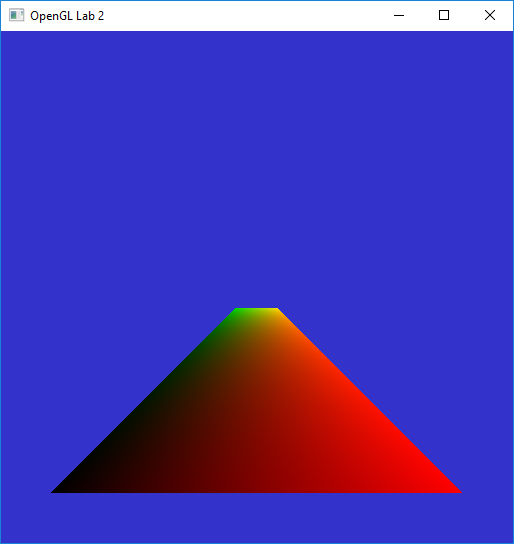
Now we can text that the texture coordinates work by pretending that they are colors and making sure we get the correct result. Change the fragment shader to be:
void main()
{
	fragmentColor = vec4(texCoord.x, texCoord.y, 0.0, 0.0);
}
Task 2: Loading a texture
To read a texture image from a file, we use stb_image, which is a header-only library in the public domain for reading and writing many image formats. We can load a texture that is in the lab2 directory with the following lines:
// >>> @task 2.1
int w, h, comp;
unsigned char* image = stbi_load("../lab2-textures/asphalt.jpg", &w, &h, &comp, STBI_rgb_alpha);glGenTextures(1, &texture);glBindTexture(GL_TEXTURE_2D, texture);
glTexImage2D(GL_TEXTURE_2D, 0, GL_RGBA, w, h, 0, GL_RGBA, GL_UNSIGNED_BYTE, image);
free(image);
glTexParameteri(GL_TEXTURE_2D, GL_TEXTURE_WRAP_S, GL_CLAMP_TO_EDGE);
glTexParameteri(GL_TEXTURE_2D, GL_TEXTURE_WRAP_T, GL_CLAMP_TO_EDGE);
We also have to set up texture filtering. We will talk more about that later. For now, just add the lines:
glTexParameteri(GL_TEXTURE_2D, GL_TEXTURE_MIN_FILTER, GL_NEAREST);
glTexParameteri(GL_TEXTURE_2D, GL_TEXTURE_MAG_FILTER, GL_NEAREST);
Task 3: Sampling the texture in the shader program
In shaders, textures are sampled from a texture unit. To sample an specific texture, we need to bind it to a texture unit. Before our draw call in the display() function, we make sure to bind our texture (texture id in the varaiable texture to texture unit 0. Add the following call, just before draw call glDrawElements():
// >>> @task 3.1
glActiveTexture(GL_TEXTURE0);
glBindTexture(GL_TEXTURE_2D, texture);
In the fragment shader (file simple.frag) add a so called sampler. I.e., inform that the shader will use a texture that is connected to texture unit 0. You do this by adding to the fragment shader:
// >>> @task 3.4
layout(binding = 0) uniform sampler2D colortexture;// >>> @task 3.5
fragmentColor = texture2D(colortexture, texCoord.xy);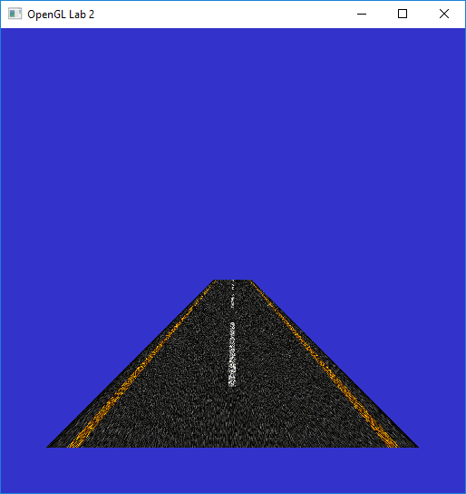
Task 4: Repeating the texture
Not as awesome as you hoped? Stretching a single road tile over the whole road is not exactly what we wanted is it? The floor is much longer than it is wide (20 units wide and 300 units long to be exact) but we map the square texture one-to-one on the quad, so the texture will be very stretched out. Instead, lets repeat the texture several times in the z-direction. Change the texture coordinates from task 1.1 as follows:
// >>> @task 1.1
float texcoords[] = {
	0.0f, 0.0f,	// (u,v) for v0
	0.0f, 15.0f,	// (u,v) for v1
	1.0f, 15.0f,	// (u,v) for v2
	1.0f, 0.0f	// (u,v) for v3
};
Now run the program. Apparently, we need to tell OpenGL what to do with texture coordinates outside the (0,1) range. Replace the texture parameters from task 2.1 (just after loading the texture) with the following parameters:
// >>> @task 1.1
//Indicates that the active texture should be repeated,
//instead of for instance clamped, for texture coordinates > 1 or <-1.
glTexParameteri(GL_TEXTURE_2D, GL_TEXTURE_WRAP_S, GL_REPEAT);
glTexParameteri(GL_TEXTURE_2D, GL_TEXTURE_WRAP_T, GL_REPEAT);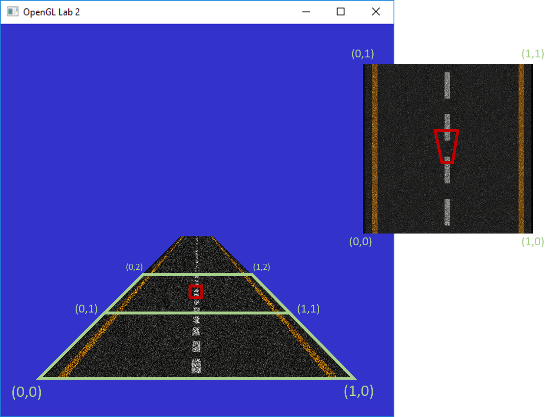
Task 5: Texture filtering
To improve the image we are now going to look at texture filtering. A problem we have run into is that parts of the texture are being shrunk to a much smaller size than the original image. So, when fetching a color from the texture for a pixel, the texture coordinate could actually map to any texel in a large area on the texture, but it will simply pick the texel on the texture coordinate that the middle of the pixel maps to.
A simple way to improve the result is to use mipmapping. Replace your glTexParameter(..., GL_NEAREST) calls with:
glGenerateMipmap(GL_TEXTURE_2D);
// Sets the type of filtering to be used on magnifying and
// minifying the active texture. These are the nicest available options.
glTexParameteri(GL_TEXTURE_2D, GL_TEXTURE_MAG_FILTER, GL_LINEAR);
glTexParameteri(GL_TEXTURE_2D, GL_TEXTURE_MIN_FILTER, GL_LINEAR_MIPMAP_LINEAR);
The call to
glGenerateMipmap() generates the mipmap levels on the bound textures. The following two lines tell OpenGL to use the mipmap when minimizing a texture and to do linear filtering when magnifying. Run the program again.
You will notice that the image is now a lot less noisy, but that its mostly a blur far away. Add this line as well:
glTexParameterf(GL_TEXTURE_2D, GL_TEXTURE_MAX_ANISOTROPY_EXT, 16.0f);
To be able to get a feel for the difference between the different filtering methods, use ImGui to easily switch between them. Uncomment the gui() call in
the main loop, a skeleton has been provided with radio buttons and a slider. Now implement what should happen when you press the different buttons or drag the
slider, it should correspond to the description already next to them. Hint: the radio buttons are just numbered from zero and up for magnification and
minification respectively.
Task 6: Transparency
No game, no matter how fake, is complete without an explosion. We will create one by drawing a new quad and texture it with a picture of an explosion. Create a new vertex array with data for positions and texture coordinates so it looks something like the image below. Also load a new texture (“explosion.png”) and use it when drawing the new quad.
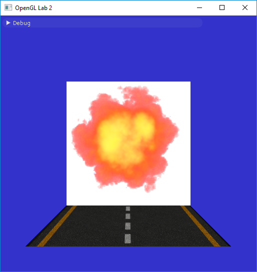
When you are done, you should see something like the image above. This texture has an alpha channel as well as color channels. The alpha channel simply says how transparent each texel is. To get the transparent effect, we will have to enable blending. Add the following lines in function display() somewhere before the call to your second glDrawElements(). The first line enables blending. The second specifies how the blending should be done. With these parameters the destination will receive an interpolated color value of:
, which faithfully corresponds to the behavior of transparency.
glEnable(GL_BLEND);
glBlendFunc(GL_SRC_ALPHA, GL_ONE_MINUS_SRC_ALPHA);
Note that to get correct transparent behavior, all overlapping transparent objects/polygons should be rendered in back-to-front order. It is common to first render all non-transparent objects in any order, and then sort all transparent objects/polygons and render them last. This transparency calculation does not require the presence of any alpha channel in the framebuffer.
Now run the program again and enjoy the exciting scene.